 |
|||
|
|
|||
|
|
|||
| ||||||||||
|
|
 TM 10-3930-632-34
a.
d.
To remove the float axle, press a screwdriver
Inspect all parts of the carburetor for wear,
against the float axle at the slotted side of the float hinge
distortion, cracks, breaks, or other damage.
bracket. Remove the axle from the opposite side and
remove the float (12).
6-6.
Reassembly
b.
After the float is removed, take care that the
fuel valve does not drop from the valve seat.
Refer to figure 6-1 to reassemble the carburetor.
c.
Use a file to match-mark the throttle lever on
Reassembly is the reverse of disassembly. Note the
the throttle shaft and the throttle body. These marks will
following:
serve as a guide to assure that the parts will be
reassembled in the proper manner.
a.
During reassembly, align the match-marks
d.
Use a file to match-mark the choke bracket,
made during disassembly on the fuel bowl, choke
choke lever, and the boss on the fuel bowl. These marks
bracket, and choke shaft and lever.
will serve as a guide to assure proper reassembly.
b.
Align the match-marks made at disassembly
e.
To remove the plug, insert a 1/4 inch rod, 6
on the throttle body and throttle shaft and lever.
inches long, through the opposite side of the fuel bowl
c.
Note that the screw holes in the throttle plate
and drive out the plug.
are off-centered. Start the side of the throttle plate with
the shortest distance between the screw holes and
WARNING
beveled edge in to place first. The plates are made with
two opposite edges beveled to fit the throttle body bore
Dry cleaning solvent, P-D-680, used to clean
when the plate is closed. The throttle plate will not close
parts is potentially dangerous to personnel and
tightly if installed upside down. Pressure on the plate
property. Avoid repeated and prolonged skin
must be maintained with the finger until the screws are
contact. Do not use near open flame or
excessive heat. Flash point of solvent is 100 F.
tightened. When properly installed, the side of the throttle
- 138 F. (39 C. - 59 C.).
plate farthest away from the mounting flange will be
aligned with the idle discharge holes when the plate is
closed.
6-5.
Cleaning and Inspection
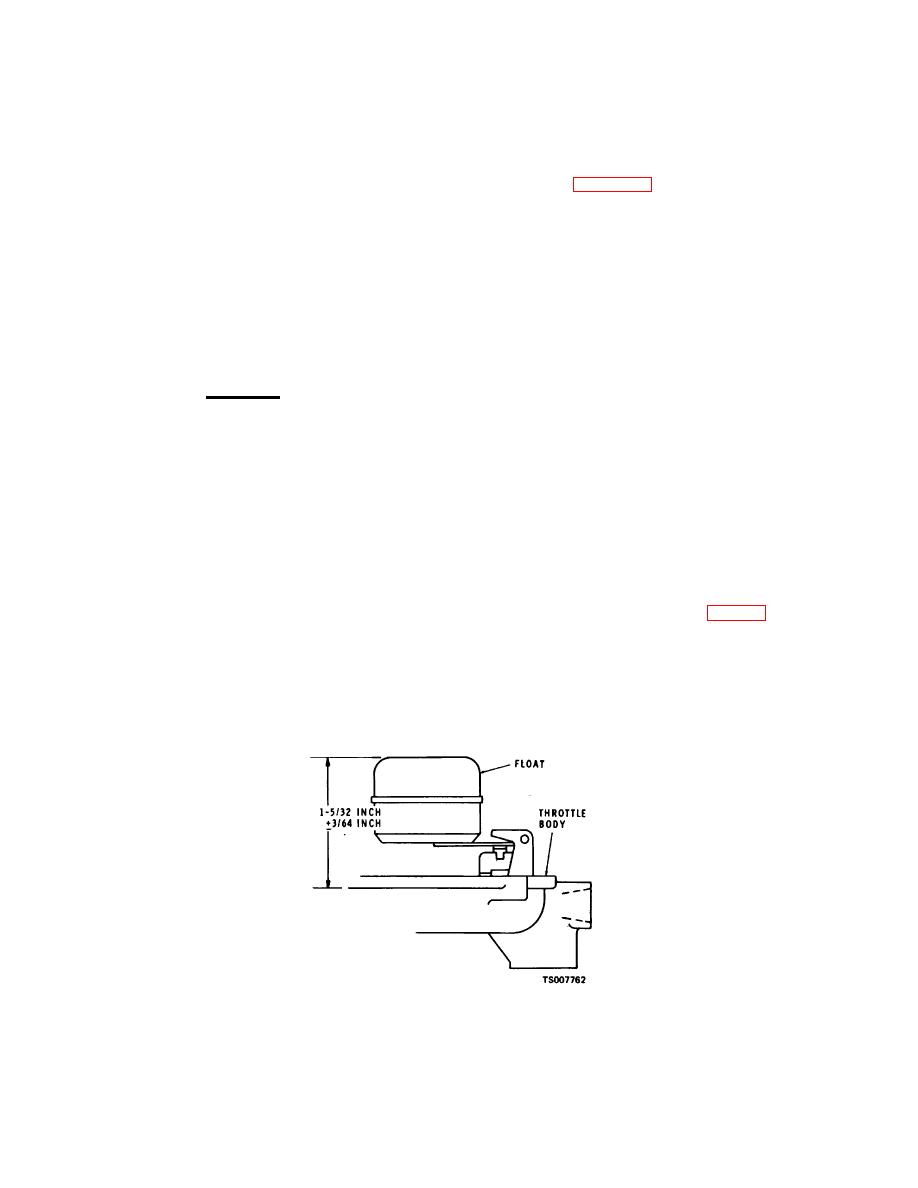
d.
After installing the float (12) and axle, check
the position of the float. With the throttle body in an
a.
Discard all washers and gaskets. Replace
inverted position and viewed from the free end of the
these parts with new ones from the repair kit.
float, the float bodies must be centered and at right
b.
Clean all parts in cleaning solvent P-D-680 and
angles to the machined surface (fig. 6-2). The distance
dry thoroughly with compressed air.
from the machined surface of the throttle body to the top
c.
Blow out all passages in the air intake, fuel
side of the highest point of the float bodies must be 1-
bowl, and throttle body with compressed air.
5/32 + 3/64 inches. To increase or decrease the distance
between the float body and machined surface, use long-
CAUTION
nosed pliers and bend the lever close to the float body.
Do not clean by inserting a wire or drill into any
openings or passages as this will destroy their
fine calibration.
Figure 6-2. Float Level Adjustment.
6-3
|
|
Privacy Statement - Press Release - Copyright Information. - Contact Us |
