 |
|||
|
|
|||
|
Page Title:
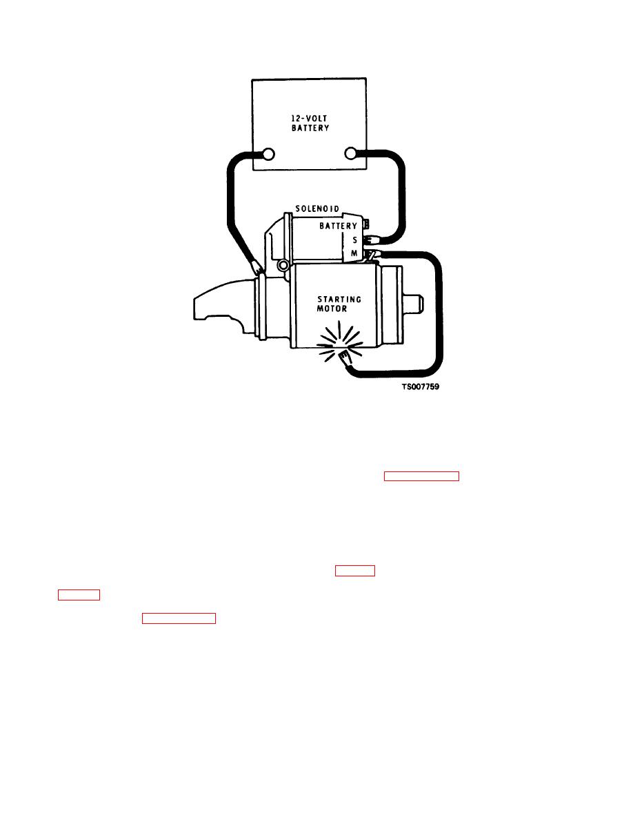
Figure 5-3. Circuit for Checking Pinion Clearance. |
|
||
| ||||||||||
|
|
 TM 10-3930-632-34
Figure 5-3. Circuit for Checking Pinion Clearance.
alignment of the collar (23) on the retaining ring (24).
CAUTION
I.
Before installation, test the engine starter as
directed in paragraph 5-12, below.
Insulate the motor field lead carefully to avoid
arcing during the checking procedure.
5-12.
Testing
g. Momentarily touch the jumper lead from the
To assure that the engine starter is fully restored to
solenoid motor terminal to the motor frame. This will
operating condition after overhaul, test it as follows:
shift the pinion into cranking position. It will stay in this
a. Connect the engine starter, a 12-volt battery, an
position until the battery is disconnected.
h. Push the pinion back toward the commutator
end to eliminate all slack movement. Measure the
distance between the pinion gear of the drive assembly
resistance until the voltmeter reads 9 volts.
The
(26, fig. 5-2) and the collar (23). If clearance is not
ammeter must read between 50 and 80 amperes and the
between 0.010 and 0.140 inch, disassemble the starting
armature speed must be between 5500 and 10,500 RPM
motor as described in paragraph 5-9 above and check
as indicated on a tachometer held against the shaft.
|
|
Privacy Statement - Press Release - Copyright Information. - Contact Us |
