 |
|||
|
|
|||
|
Page Title:
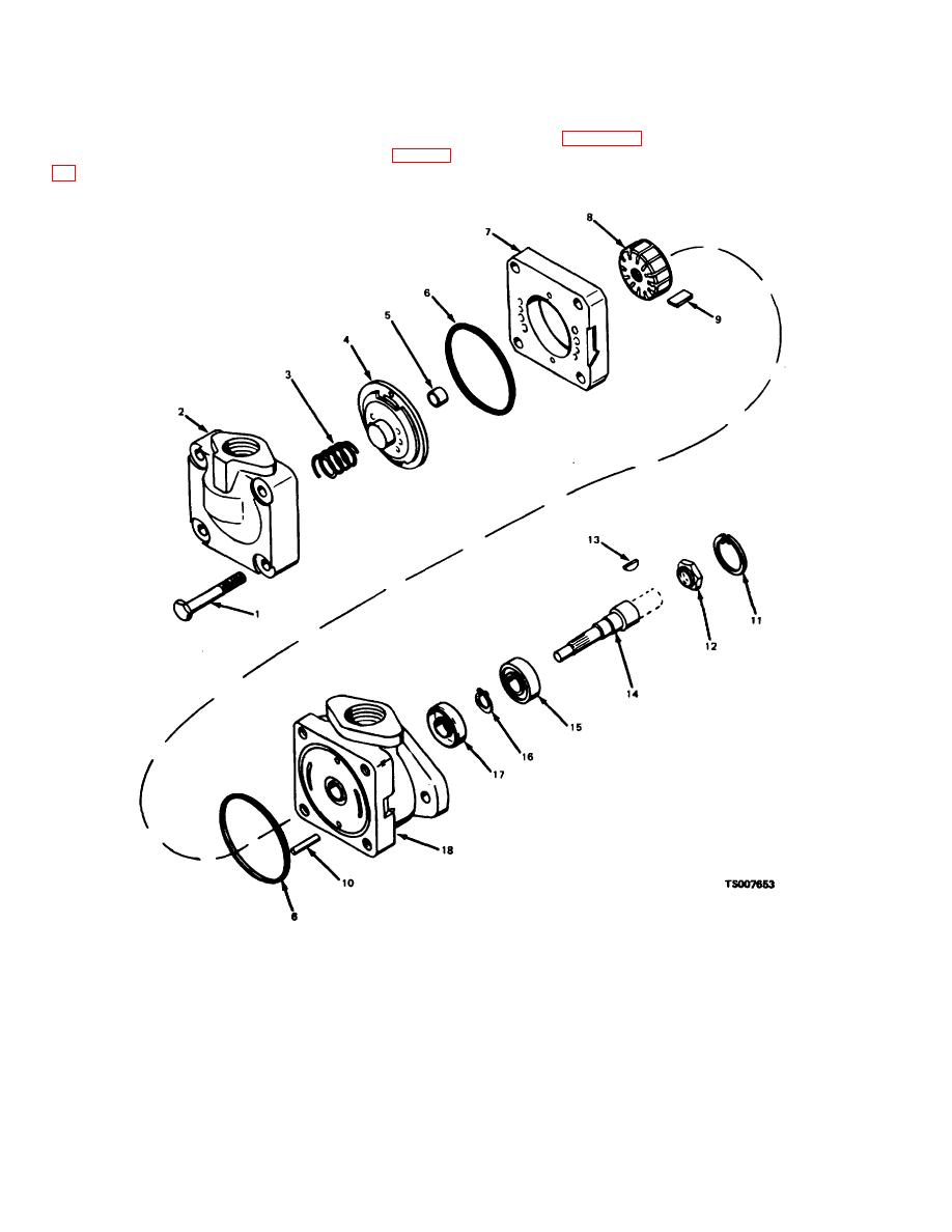
Figure 4-2. Hydraulic Pump, Exploded View. |
|
||
| ||||||||||
|
|
 TM 10-3930-632-34
4-9.
Removal
4-10.
Disassembly
Remove the gear cover and the hydraulic pump with its
Refer to figure 4-2 and disassemble the main hydraulic
assembled adapter and gasket from the engine (para 9-
pump. Note the following:
1.
screw
7.
rump ring
13.
Woodruff key
2.
Pump cover
8.
Rotor
14.
Pump shaft
3.
Spring
9.
Vane
15.
Bearing
4.
Pressure plate
10.
Pin
16.
Retaining ring
5.
Bushing
11.
Retaining ring
17.
Shaft seal
6.
Preformed packing
12.
Nut
18.
Pump body
Figure 4-2. Hydraulic Pump, Exploded View.
4-4
|
|
Privacy Statement - Press Release - Copyright Information. - Contact Us |
