 |
|||
|
|
|||
|
Page Title:
Steering Axle Linkage Adjustment. |
|
||
| ||||||||||
|
|
 TM 10-3930-632-34
jack and remove the four bolts and lockwashers that
secure the steering axle assembly to the axle mounting
blocks. Lower the steering axle assembly to the floor.
Remove the two cotter pins, washers, and nuts that
secure the axle mounting blocks to the frame; remove
the blocks.
b. Installation.
(1) Position the axle mounting blocks (14, fig. 13-1)
into the holes provided in the fork lift truck frame and
secure with the nut (11) and cotter pin (10). Raise the
steering axle assembly so that the brackets provided on
it are in line with the axle mounting blocks. Secure the
steering axle assembly to the axle mounting blocks with
the four screws (12) and lockwashers (13). Torque to
130 to 140 ft/lbs.
(2) Connect the rear drag link to the ball stud (TM
10-3930-632-12).
(3) Replace the wheel assemblies (TM 10-3930-
632-12).
c. Steering Axle Linkage Adjustment.
(1) Remove the counterweight (TM 10-3930-632-
12).
(2) Install a jack under the center rear of the frame
or use a hoist and sling with spreader bars hooked in the
lifting recesses of the rear wheel well. Raise the rear of
the fork lift truck and install wooden blocks ahead of the
rear wheels under the sides of the frame.
(3) Remove the rear drag link from the steering axle
spider ball stud.
(4) Check the steering wheels for correct turning
geometry, by turning the wheels all the way to the left.
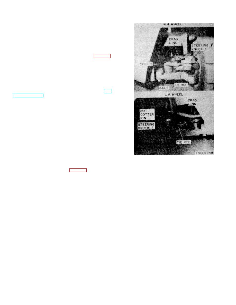
Figure 2-13. Steering Axle and Linkage Adjustment.
This should allow the righthand steering wheel to attain
an angle of 75 degrees to the frame. If adjustment is
(5) After adjusting the stop screws, check steering
necessary, the axle stop screw (fig. 2-13) on the front
wheel alignment. Place the steering wheels in the
side of the steering knuckle should be turned in or out,
straight-ahead position. The steering wheels should
whichever is necessary to achieve the correct angle.
track squarely with the drive wheels with no toe-in or toe-
Repeat this procedure with the left wheel.
out. If adjustment is necessary, adjust the alignment of
the steering wheels by
2-21
|
|
Privacy Statement - Press Release - Copyright Information. - Contact Us |
