 |
|||
|
|
|||
|
Page Title:
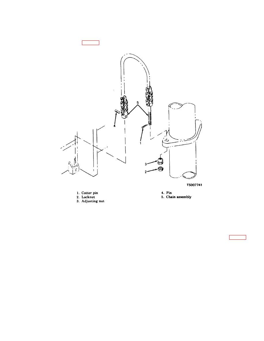
Figure 2-6. Chain Anchors, Removal and Installation. |
|
||
| ||||||||||
|
|
 TM 10-3930-632-34
(2) Position blocks under the carriage assembly
and 3) that secure the lift chain assemblies (5) to the
and lower the carriage assembly until it rests firmly on
hydraulic lift cylinder; remove lift chain assemblies from
the blocks.
the hydraulic lift cylinder and lay them over the carriage
(3) Remove the cotter pins (1, fig. 2-6) and nuts (2
assembly.
Figure 2-6. Chain Anchors, Removal and Installation.
(4) Start the engine; using the hydraulic control
Disconnect the cylinder hose assembly from the elbow.
valve, raise the mast assembly until the carriage
(6) Support the hydraulic lift cylinder with a hoist,
assembly, is clear of the mast assembly. Remove the
using a sling wrapped around the cylinder under the
carriage assembly from the fork lift truck.
chain bracket. Remove the two capscrews (1, fig. 2-7),
(5) Provide a container to catch the hydraulic oil as
nuts (3), and lockwashers (2) that hold the adapter (4)
the hydraulic connection to the inlet elbow is broken.
into the bracket on the mast.
2-11
|
|
Privacy Statement - Press Release - Copyright Information. - Contact Us |
