 |
|||
|
|
|||
|
Page Title:
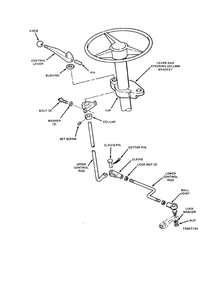
Figure 4-61. Directional Shift Lever and Linkage |
|
||
| ||||||||||
|
|
 TM 10-3930-632-12
Figure 4-61. Directional Shift Lever and Linkage
b. Insure that center of shift lever knob is 2.40
d. If a binding condition exists, adjust linkage to
inch to 2.90 inch in front of steering column centerline
free binding.
It must operate smoothly and
with transmission in neutral position.
engage/disengage transmission completely.
c. Check to see that there is 3 inch minimum
clearance between steering wheel and shift lever knob.
4-78
|
|
Privacy Statement - Press Release - Copyright Information. - Contact Us |
