 |
|||
|
|
|||
|
|
|||
| ||||||||||
|
|
 TM 10-3930-632-12
b. Installation. Installation may be
accomplished by reversing the procedures outlined in
figure 4-62.
4-76. Service Brakes
Paragraph 4-75.a through c. (3) deleted.
Figure 4-53 deleted.
d. Bleeding Brake System. Whenever the
brake system is opened for any reason, such as repairs
to master cylinder, wheel cylinder, valves or tubing, air
will enter the brake system and must be expelled
through the bleeding procedure outlined in the following
paragraphs.
Pressure bleeding, as outlined in
paragraph (1) is the preferred method if the proper
equipment is available.
(1) Pressure Bleeding. Make certain that
the pressure bleeding equipment will hold enough of the
right type of brake fluid to do the job (about 2 quarts).
Do not intermix different types of brake fluid, and never
reuse fluid that has been drained from the brake system.
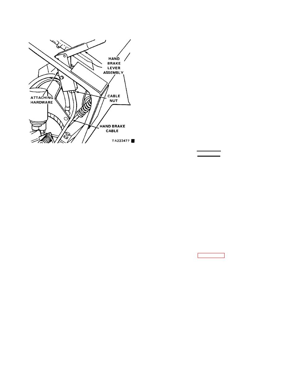
Figure 4-52. Hand Brake Lever, Removal and
WARNING
Installation
Make certain that pressure bleeder tank is
certified for use at pressures exceeding 30
PSI before using.
(a) Clean all dirt, grease, etc., from
around the master cylinder reservoir cap on both the
brake and inching master cylinder.
(b)
Remove the master cylinder
reservoir cap and fill reservoir with SAE 70 R3 Heavy
Duty Hydraulic Brake Fluid to within /4 inch from the top
of the reservoir.
(c) Fill the pressure bleeder reservoir
with about 2 quarts of the same fluid, and pressurize the
tank to NOT MORE than 30 PSI.
(d) Place a flat pan under the axle
adapter to catch brake fluid spillage, and connect the
pressure bleeder line to the brake master cylinder.
Open the pressure bleeder valve.
(e)
With the bleeder hook-up
completed as shown in figure 4-54, open bleed points B
and C and allow fluid to flow from loosened fittings until
no further bubbles appear in the flow. Tighten fittings
securely when all air is expelled.
Change 2 4-67
|
|
Privacy Statement - Press Release - Copyright Information. - Contact Us |
