 |
|||
|
|
|||
|
Page Title:
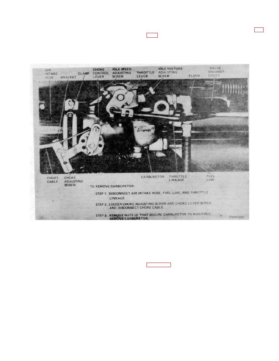
Figure 4-29. Carburetor, Adjustment Points, Removal and Installation |
|
||
| ||||||||||
|
|
 TM 10-3930-632-12
(5) Loosen the choke adjusting screw (fig.
(2) Remove a pipe plug from the intake
manifold; install an adapter in the pipe plug hole;
pull it out about 1/16-inch. Push the choke control lever
connect a vacuum gage to the adapter.
(3) Connect a tachometer to the engine.
as far as possible toward the rear of the fork lift truck;
secure the choke adjusting screw against the choke
(4) Run the engine at fast idle-until it is at
wire.
operating temperature.
Figure 4-29. Carburetor, Adjustment Points, Removal and Installation
(6) Set the idle speed adjusting screw for
(9) If any idle speed readjustment is
an engine speed of 450 to 500 RPM.
necessary, readjust the idle mixture as directed in (7)
(7) Set the idle mixture adjusting screw to
above.
b. Removal.
obtain the highest reading possible on the vacuum gage.
(8) If engine speed is not between 450 to
(1) Remove the fuel cap and well shown in
500 RPM, reset the engine idle speed as directed in (6)
above.
4-43
|
|
Privacy Statement - Press Release - Copyright Information. - Contact Us |
