 |
|||
|
|
|||
|
Page Title:
Section XIII. ELECTRICAL SYSTEM |
|
||
| ||||||||||
|
|
 TM 10-3930-632-12
c. Cleaning.
idle speed, raise and lower the carriage and operate the
tilt cylinder. Refill the hydraulic tank. Check for leaks.
(1) Discard and replace the filter element
and gaskets.
4-29. Hydraulic Reservoir Breather
(2) Clean metal filter components with dry
cleaning solvent P-D-680; dry with clean, dry
a. Removal. Remove the hydraulic reservoir
compressed air. Clean the interior of the hydraulic tank
with a clean cloth. Rinse with 2 quarts of hydraulic oil.
breather (fig. 4-12) by unscrewing it from the hydraulic
(3) Inspect the filter case for cracks,
reservoir filler pipe.
b. Cleaning. Clean the hydraulic reservoir
distortion, damaged mounting flange, and other
damage; replace if damaged.
breather by tapping it on a wood block or bench while
(4) Inspect the cover for cracks, scored or
rotating the breather. This procedure is intended to
damaged outlet connection, studs that are loose or have
dislodge particles caught in the air filter. Replace the
damaged threads, or a damaged mounting flange.
breather after it has been in service for 500 operating
d. Reassembly. Reassemble the filter as
hours.
shown in figure 4-12.
e. Refilling Hydraulic Tank. Fill the hydraulic
tank to the bottom of the filler tube. With the engine at
Section XIII. ELECTRICAL SYSTEM
4-30. General
The electrical wiring diagram for the fork lift truck is
shown in figure 1-3. Power to operate the starting motor
is supplied by a 12-volt battery. When the starter and
ignition switch is turned to START, the starter relay is
energized, provided the direction control lever is in
neutral so that the neutral start switch is closed. The
starter relay closes the circuit that energizes the starter
solenoid. The starter solenoid then completes a circuit
from the battery to the starting motor to crank the
engine. When the engine is running, it turns the
the instrument panel indicates the rate of charge. The
headlight and taillight are operated by the light switch
mounted on the instrument panel. The stoplight is
operated by a pressure switch mounted on the brake
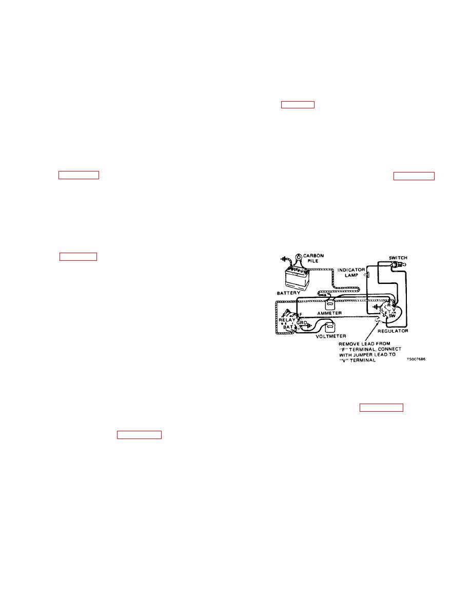
Figure 4-13. Alternator Output Test Setup
master cylinder. This circuit closes only when the
starter and ignition switch is in the run position.
(2) To check operation of field relay, make
4-31. Alternator
meter connections as shown in figure 4-14, connecting
a. Test.
the voltmeter from field terminal of regulator to ground.
Turn on ignition switch, but do not start engine. The
(1) To test alternator output, make meter
voltmeter should indicate battery voltage.
If the
connections as shown in figure 4-13. The carbon pile
voltmeter indicates zero, the field relay is defective.
rheostat across the battery terminals provides an
artificial load for the alternator to work against. Run
engine up to governed speed and check alternator
output. Output should be: 8 Amps @ 80F.-500 Engine
RPM; 31 Amps @ 80F.-2200 Engine RPM.
Change 1 4-29
|
|
Privacy Statement - Press Release - Copyright Information. - Contact Us |
