 |
|||
|
|
|||
|
Page Title:
Section XII. HYDRAULIC LIFT COMPONENTS |
|
||
| ||||||||||
|
|
 TM 10-3930-632-12
disassembly. If any tags were destroyed, refer to the
overheating, damaged threads, and other damage;
replace damaged switches.
wiring diagram (fig. 1-3} to determine the connection
requirements.
(5)
Inspect the instrument panels for
cracks, dents, distortion, and other damage; replace
(3) Install the instrument panel as shown in
damaged instrument panels.
d. Testing. Proper operation and function of
c. Reassembly and Installation.
the gages can be tested by running the truck engine and
(1) Reassemble the instrument panel as
observing all gages. Check the fuel gage, ammeter, oil
shown in figure 4-5.
gage, and temperature gage for proper readings.
(2) Connect the electrical leads following
the instructions on the tags that were installed at
Section XII. HYDRAULIC LIFT COMPONENTS
4-23. General
The hydraulic lift system consists of a hydraulic pump,
oil reservoir, control valve, lift cylinder, tilt cylinders, and
a tilt-lock valve, together with their connecting hoses
and tubes. Hydraulic oil is drawn from the reservoir by
the pump which is mounted on the engine front cover.
The oil is forced through a high pressure line to the
control valve. When the lift and tilt control levers are in
neutral position, oil flows through the valve and back to
the reservoir. When one of the control levers is
depressed, oil is diverted through tubes and hoses to the
corresponding cylinder and the desired motion is
performed. When the limit of this motion or stroke is
reached (piston rod fully extended or retracted),
pressure built up in the system to approximately 2000
PSI forces a plunger in the relief valve section of the
control valve to open and return excess oil to the
reservoir. The tilt-lock valve prevents the flow of oil to
and from the tilt cylinders when the hydraulic system is
not pressurized even though the control valve lever is
depressed. This prevents tilting of the mast when the
engine is not running.
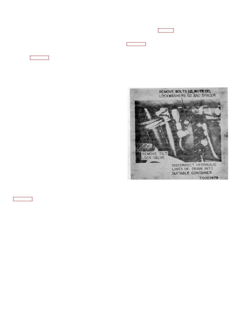
Figure 4-6. Tilt-Lock Valve, Removal and Installation
4-24. Tilt-Lock Valve
a. Removal. Remove the tilt-lock valve as shown in
4-21
|
|
Privacy Statement - Press Release - Copyright Information. - Contact Us |
