 |
|||
|
|
|||
|
Page Title:
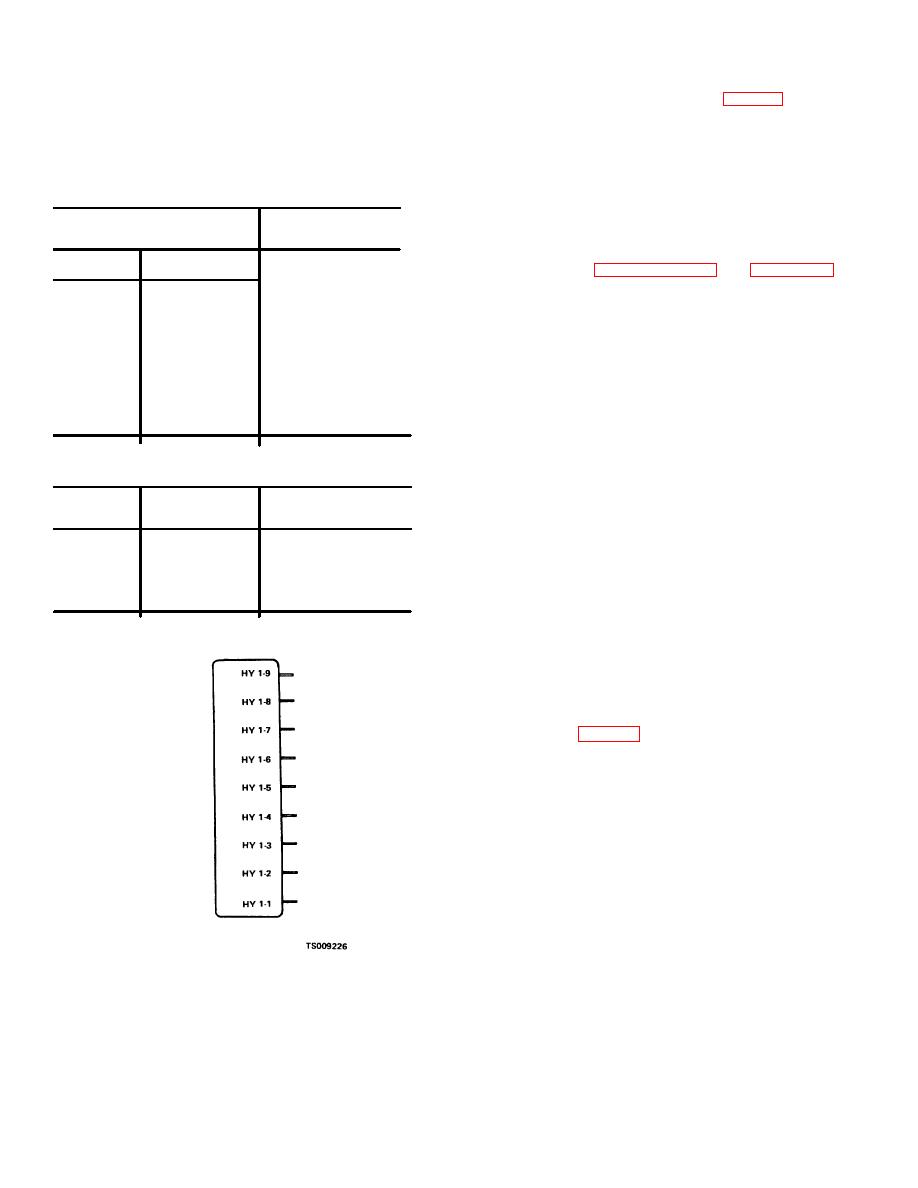
Table 9-1. Diode Suppressor Module Tests |
|
||
| ||||||||||
|
|
 TM 10-3930-631-34
left corner of the contactor panel (fig. 2-7). Disconnect
Note
the battery and discharge capacitors. Disconnect the
If any of the readings are not obtained, the diode
wires from the top (anode) of the diodes to isolate them.
suppressor module must be replaced (para. 9-
Connect ohmmeter leads as follows to determine if
24).
diodes are blocking and are in proper polarity.
b. Set the multimeter on the RX1 scale. Touch the
Table 9-1. Diode Suppressor Module Tests
positive lead to the anode and the negative lead to the
cathode. Reading should be low resistance. Touch the
VOM Connection
Reading
positive lead to the cathode and the negative lead to the
(RX1 scale)
anode. Reading should be infinity.
c. Refer to paragraph 9-14 and figure 9-9 and
Positive lead
Negative lead
check diode for blocking capability.
9-19. Positive Temperature Coefficient Resistor
HY1-3
HY1-5
Low resistance
HY1-5
HY1-3
High resistance
Test
HY1-7
HY1-8
Low resistance
a. The positive temperature coefficient resistor is
HY1-8
HY1-7
High resistance
mounted on the heatsink at the end of the static panel. It
HY1-7
HY1-6
Low resistance
is a temperature sensitive device which increases in
HY1-6
HY1-7
High resistance
resistance with an increase in tem- perature. As the
HY1-4
HY1-9
45-120 ohms
temperature of the heatsink increases, the resistance of
HY1-9
HY1-4
High resistance
the resistor increases. Since the resistor is wired into the
circuit of the control module, this increased resistance
VOM Connection
Reading
decreases the speed of the lift truck. The lift truck will
(RX1 scale)
operate at a reduced speed until the heatsink
temperature drops to a normal value; then once again
Positive lead
Negative lead
full speed is available.
b. Disconnect yellow wires from the resistor and
HY1-1
HY1-2
20K to infinity
connect a VOM set on RX1 scale to the resistor
HY1-2
HY1-1
20K to infinity
terminals (PR1 and PR2). Reading should be less than
HY1-3
HY1-4
20K to infinity
200 ohms if heatsink is at room temperature
HY1-4
HY1-3
20K to infinity
(approximately 700F (21 C). Set VOM on highest ohms
scale and check each terminal to heatsink resistance;
both readings should be infinity.
9-20. Capacitors
a. One method of checking C1 thru C5 capacitors
to determine if they are good is as follows:
b. Connect a fully charged test battery or lift truck
battery, a 10K ohm resistor in series, and a voltmeter to
the capacitor (fig. 9-11), but do not connect the negative
lead to the battery. Use a watch with a sweep second
hand to time the period of charging. Now connect the
negative lead to the battery and begin timing. After 37
seconds, the capacitor voltage should be approximately
22 volts ( 4 volts).
Figure 9-10.Diode suppressor module.
9-18. D3 and D4 Diode Test
a. D3 and D4 diodes are located at the upper
9-16
|
|
Privacy Statement - Press Release - Copyright Information. - Contact Us |
