 |
|||
|
|
|||
|
Page Title:
Plugging Potentiometer Adjustment |
|
||
| ||||||||||
|
|
 TM 10-3930-631-34
d. Adjust inching potentiometer to desired
tested, remove braided cathode lead of diodes (fig. 9-6)
from terminal studs to isolate the diodes. Use diode
performance or so lift truck inches along with
block as anode for testing D1 and D2 diodes.
accelerator pedal slightly depressed.
To adjust
b. The following ohmmeter test for a diode will
potentiometer, loosen locknut and turn inching
determine if it is blocking and in proper polarity. Touch
potentiometer shaft {fig. 9-3) clockwise to in- crease'
positive lead of multimeter to anode and negative lead to
inching or counterclockwise to decrease it.
After
cathode. Reading should be low resistance. Touch
adjustment is completed, hold potentiometer shaft in
positive lead to cathode and negative lead to anode.
place and tighten locknut to prevent shaft from turning
Reading should be infinity. If above reading are not
out of adjustment.
obtained, replace
9-14. Plugging Potentiometer Adjustment
diode (para. 9-28).
a. Slowdown is accomplished when a direction is
c. Whenever stud type D1 and D2 diodes are
reversed by providing a small amount of retarding
replaced, it is recommended that a heat transfer grease
torque for deceleration. If the lift truck is moving, the
(silicon compound, or an equivalent) is used between
accelerator pedal is released, the forward and reverse
the stud of the diode and the diode block. Diodes
lever is moved from forward to reverse, and the
should be screwed into the diode block and tightened to
accelerator pedal is then depressed again, the motor
a torque of 275-325 pound- inches (2.30-2.79 m-kg).
field is reversed. The distance or severity of the
d. The diodes can be checked further to assure
reversal is adjustable
by means of a plugging
the diode does not conduct current in the reverse
potentiometer.
direction of battery voltage.
b. After tests are completed and drive wheels are
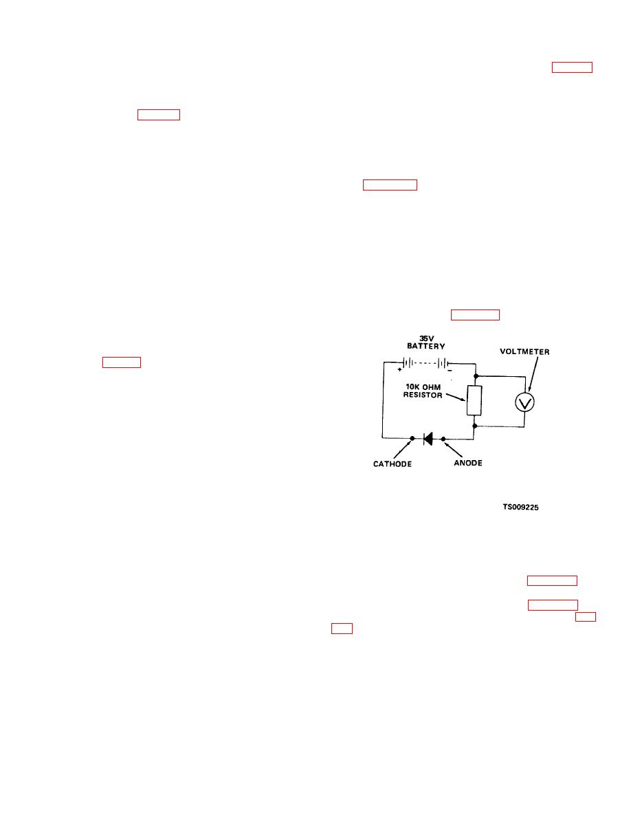
e. Connect battery, a 10K ohm resistor, voltmeter
lowered to the floor, operate lift truck and plug it at full
and diode as illustrated in figure 9-9.
speed. If stopping distance is too short or too long,
adjust plugging potentiometer until desired stopping
distance is obtained.
c. Adjust the plugging with the plugging
potentiometer (fig. 9-3) located on the side of the
speed control box.
d. Loosen locknut just enough so potentiometer
shaft can be turned. Turn plugging potentiometer shaft
clockwise for a severe
plugging condition or
counterclockwise for a soft plugging condition. After
adjustment is completed, hold potentiometer shaft in
place and tighten locknut to prevent shaft from turning
out of adjustment.
CAUTION
Plugging is a performance adjustment. It can
be adjusted for a severe or soft plug and will not
harm the control. However, if it is set too
severe, damage to the drive motor or the drive
axle may result.
9-15. Dynamic Test
Figure 9-9. Diode Test.
a. Make certain the drive wheels are completely
clear of blocks and floor and the cardboard is removed
f. If diode is good, meter should read zero voltage.
from the contactors.
If reading shows a voltage, replace diode (para 9-28).
b. Sit on the operator's seat and turn the key
9-17. Diode Suppressor Module Test
switch to the ON position. Move the forward and
a. The diode suppressor module (fig. 9-10) is
reverse lever to forward. Depress the accelerator pedal
located in the upper portion of the contactor panel (fig.
slightly until the forward contactor closes.
c. Slowly continue to depress the accelerator pedal.
ohmmeter leads as indicated in the following table.
Wheels should begin to turn and pick up speed slowly
b. Meter reading is 20K initially and then indicator
and smoothly.
should move towards infinity.
9-16. D1 and D2 Diode Test
a. Disconnect
the
battery
and
discharge
capacitors. Before D1 free wheeling and D2 armature
diodes (located on the static panel) are
9-15
|
|
Privacy Statement - Press Release - Copyright Information. - Contact Us |
