 |
|||
|
|
|||
|
|
|||
| ||||||||||
|
|
 TM 10-3930-631-34
b. Disconnect the cable which connects the B +
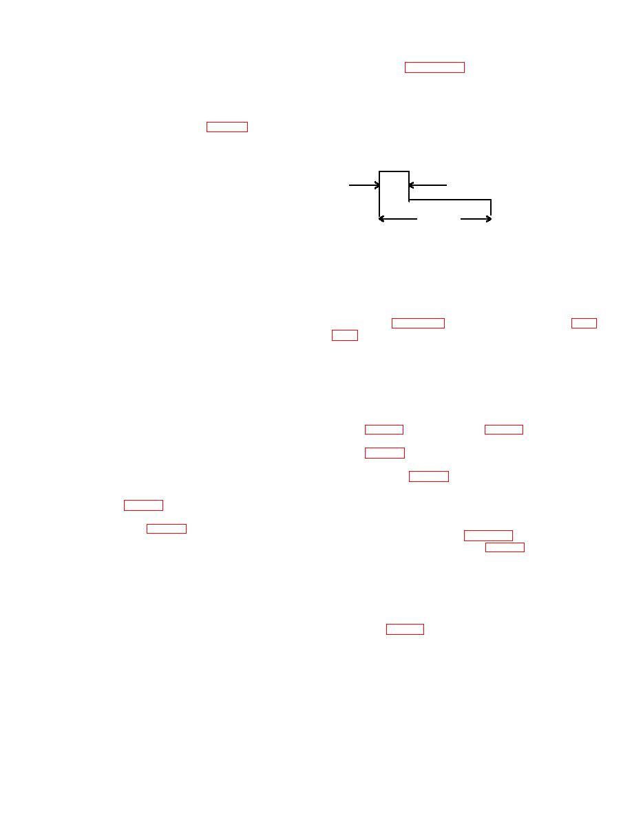
as shown on figure 9-7. The pulse width should
stud and free wheeling diode cathode to B + of the
increase with increased pedal depression.
The
capacitors from the capacitors.
maximum on time will be approximately 33 percent.
c. Utilize a multimeter to make this check:
VERTICAL 1V/CM
(1) Use the high ohms scale on multimeter.
HORIZONTAL 1MS/CM
Touch positive lead to diode block (fig. 9-6) or power
switch module frame and negative lead to B- stud.
FREQUENCY WILL BE APPROXIMATELY 275 TO
Reading should be greater than 50K ohms.
350 HERTZ
(2) Use low ohms scale. Touch positive lead to
5V
B-- stud and negative to diode block or power switch
module. Reading should be less than 100 ohms.
d. If the above readings are not obtained the
power switch modules are open, one or more are
3.3
SEC
shorted or the control board is defective. Replace
TS009223
components as necessary.
Figure 9-7. Waveform for control board output.
e. The following checks may be used to determine
the problem:
c. If the above conditions do not occur, check as
(1) To determine which power switch module is
follows.
shorted remove the bus bar mounting cap- screws and
(1) Contactors do not energize.
insulate the B- bus bar from the power switch modules.
(a) Faulty wiring-check continuity.
Perform the VOM check above and if the faulty condition
(b) Shorted diode suppressor module. Check
remains proceed to following step (2). If the shorted
the module (para. 9-17), and replace if necessary (para
condition no longer exists connect B- with a jumper wire
to each B- connection on the power switch module and
(c) Improperly adjusted or faulty speed
repeat the above VOM check until the faulty module is
potentiometer. Adjust or replace if necessary. (para 9-
found. Replace the shorted module and repeat the
12).
VOM check.
(2) No buzzing from regulators.
If the
(2) Disconnect the orange wire from the A2
contactors, energize and no audible buzzing is heard
terminal. Repeat the VOM test. If the test is satisfactory
from the drive regulators, check the continuity from the F
replace the control circuit module and repeat the VOM
or R contactor contacts thru fuses F3 to F4, diodes D3
test.
to D4 (fig. 2-8), and resistor R1 (fig. 2-8) to control plug
Note
pin P2-11. Check from P2-11 to the B + input (white/red
Connect all wires and cables before continuing
wire) (fig. 9-6) on the drive regulator modules. If the
with further tests.
fuses were blown, check diodes D3 and D4 on the
9-8. Control Board Output Test
contactor panel (fig. 2-8) and capacitor C3 on the static
Note
panel for shorts. The drive regulator may be defective.
The control board is a component of the control
Replace as necessary.
circuit module (fig. 9-6).
(3) Waveform is not as indicated.
a. Connect the positive lead of an oscilloscope to
(a) Defective positive temperature coefficient
the white wire lead S1 (fig. 9-6) on the drive regulator.
resistor. Check the resistor (para 9-19).
Connect the negative lead of the oscilloscope to B--.
(b) Undervoltage switch (fig. 9-6) on the control
(1) Connect battery.
board is in the incorrect position. Place in correct
(2) Sit on the operator's seat.
position. (36 volts).
(3) Turn the key switch to ON.
(c) Defective
wiring
harness
or
poor
(4) Put the forward and reverse lever into a
connections on the static panel. Check and repair or
direction.
replace defective connections or harness.
(5) Depress the accelerator pedal slightly to
(d) Defective control board. Disconnect the
energize the contactor.
white wire (fig. 9-6) from the S1 terminal of the #1 drive
b. The contactor should energize after a small
regulator. Connect the positive lead of the scope to the
amount of pedal depression. As soon as the contactor
white wire and observe the
energizes an audible buzzing should be heard from the
drive current regulators. The waveform observed on the
oscilloscope should be
9-12
|
|
Privacy Statement - Press Release - Copyright Information. - Contact Us |
