 |
|||
|
|
|||
|
|
|||
| ||||||||||
|
|
 TM 10-3930-631-34
the outer lever of the control valve. Pushing the lever
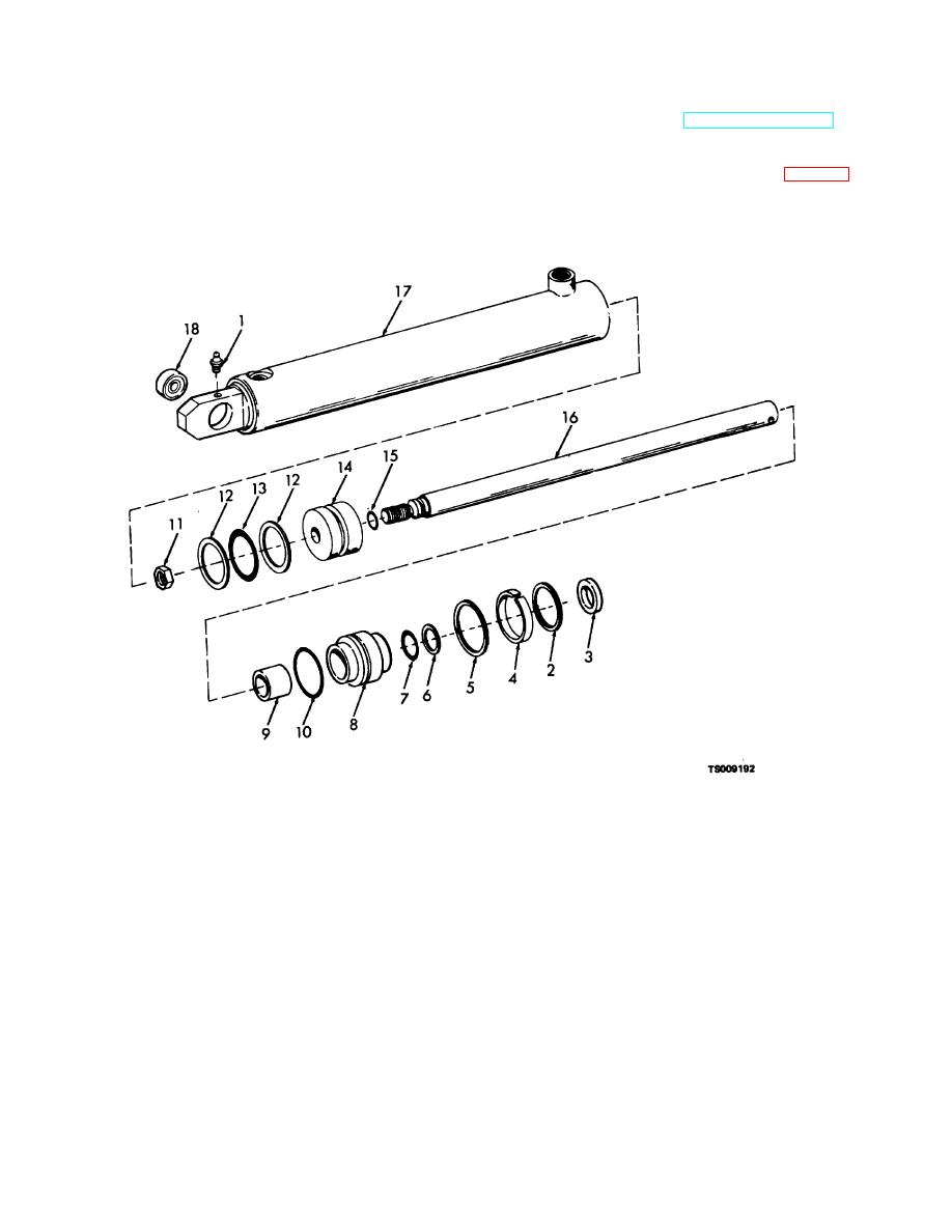
7-9. Side Shift Cylinder
forward will move the carriage to the left. Rearward
a. Removal. Refer to TM10-3930-631-12 and
movement of the lever shifts the carriage to the right.
remove the side shift cylinder.
c. The side shift cylinder is connected at one end to
b. Disassembly.
the carriage plate and the other end is anchored to the
(1) Remove lubrication fitting (1, fig. 7-14) from
frame. Hydraulic hoses leading to the cylinder are
the tube.
connected to a reel attached to the outer mast. As the
carriage is raised and lowered the hoses reel and unreel.
1.
Lubrication fitting
10.
Seal
2.
Lock ring
11.
Nut
3.
Wiper
12.
Backup washer
4.
Spacer
13.
Packing
5.
Lock ring
14.
Piston
6.
Backup washer
15.
Seal
7.
Packing
16.
Rod
8.
Head
17.
Tube
9.
Bearing
18.
Bearing
Figure 7-14. Side shift cylinder, exploded view.
7-22
|
|
Privacy Statement - Press Release - Copyright Information. - Contact Us |
