 |
|||
|
|
|||
|
|
|||
| ||||||||||
|
|
 TM 10-3930-631-34
can be pushed down evenly and flush with upper surface
(5) Replace any defective, damaged or scored
of spool and sleeve.
parts. Replace all seals and packings from kit provided.
(9) Install centering pin (21, fig. 5-4) and push
e. Assembly
into place until both ends are flush or slightly below
(1) Lubricate all parts with engine oil (OE),
sleeve diameter.
(2) Place housing (30) in a vise with upper end
(10)Place housing on a solid surface with the
of housing facing up.
port face down. Install spool assembly with splined end
(3) Install check valve spring (20) in bore of
of spool entering fourteen hole end of housing first.
housing with small end up. Install ball (28) into bore so
Push parts into place with a slight rotating motion. Make
that it rests on top f small end of spring. Check ball
certain parts do not cock out of position while installing.
action by pressing ball against spring with a small pin.
(11)Install spool assembly into housing bore until
(4) Place check valve seat (27) on hex wrench
flush with lower end of housing. When spool assembly is
and install in housing. Machined counterbore of seat
flush, check for free rotation by turning spool assembly.
must seat on ball. Tighten seat to of 150 pound inches
Hold parts in position and place on wooden block in vise.
(1.72 m/k).
Clamp vise lightly on port face of housing.
(5) Install spool (23) into sleeve (24). Spring
(12)Install new packing (25) on check valve plug
slots of both parts must be at the same end. Rotate
(26) and install plug in bore in housing. Press plug in with
spool carefully while sliding parts together. Check spool
finger pressure, rocking it slightly to prevent cutting
for free rotation. Spool must rotate freely.
packing.
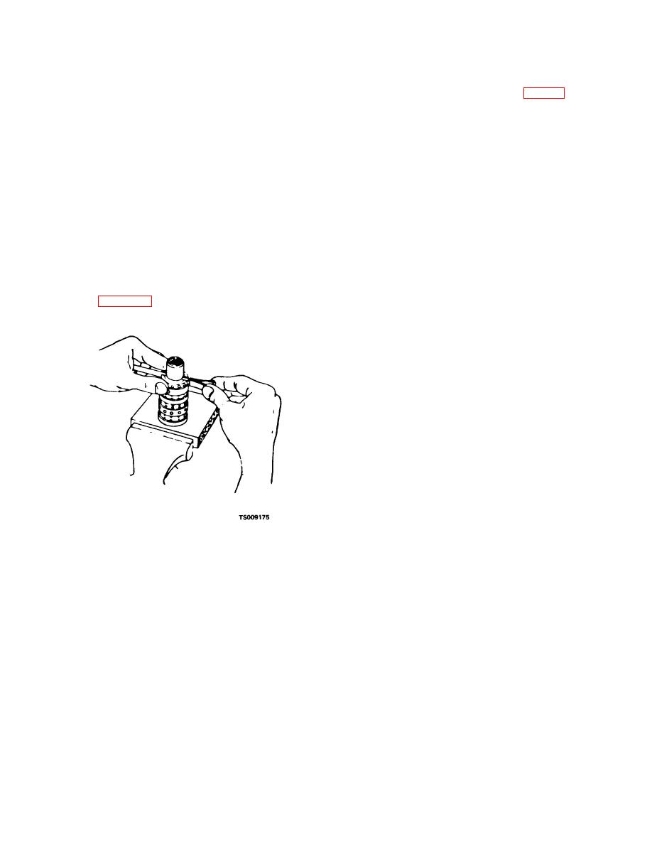
(6) With spring slots in line, stand parts on end
(13)Install bushing (19), large outside diameter
as shown in figure 5-7. Insert spring in- stallation tool
of chamfer up, partially into housing. Rotate bushing to
through slots in both parts.
seat bushing flatly and smoothly against spool assembly.
(14) Install new seal (18) on bushing. Install new
seal (15) in mounting plate (17). Push seals carefully
into seal grooves. Install seal (15) with the seal lip up.
(15)Place mounting plate (17) over spool shaft
and in place over cap locator bushing. Install carefully so
as not to displace seals.
(16)Mounting plate must fit flush against housing
assembly and locator bushing must not be cocked.
Secure mounting plate with screws (13). Tighten screws
to a torque of 250 pound inches (2.86 m/kg).
(17)Position housing in vise with lower end up.
Spool assembly must be flush with surface of housing.
Wipe surface of housing with hand to clean it. Install
plate (35) on housing.
(18)Install gear ring (part of gerotor set (34)) on
plate. Install splined end of drive gear (33) in splines of
star gear with slot in splines alined with valleys between
star gear teeth.
(19)Push splined end of drive gear through star
Figure 5-7. Installing centering spring set.
gear until approximately one-half of its length extends
beyond star gear. Install star gear in gear ring and
(7) Position three sets of centering springs on
position parts so that drive gear remains in position with
bench so that extended edge is down and arched center
star gear. Rotate gear ring slightly to engage cross slot
section are together. In this position install one end of
with centering pin in sleeve and splined end of drive gear
spring set in installation tool.
against plate.
(8) Compress extended end of centering
Note
springs and push into spool-sleeve assembly,
Proper alinement of drive gear with valleys of
withdrawing installation tool at the same time. Springs
star gear determines proper valve timing
must be centered in parts so that springs
(20)Place plate (35) on star gear. If plate
5-9
|
|
Privacy Statement - Press Release - Copyright Information. - Contact Us |
