 |
|||
|
|
|||
|
Page Title:
Cleaning, Inspection and Repair. |
|
||
| ||||||||||
|
|
 TM 10-3930-631-34
1.
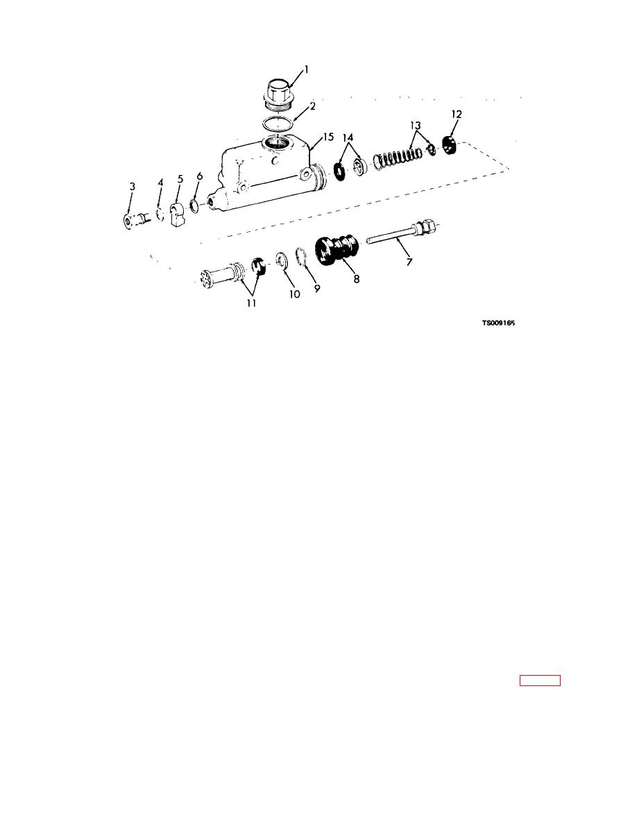
Filler cap
6. Gasket
11.
Piston assembly
2.
Gasket
7. Piston rod
12.
Cup
3.
Fitting
8. Boot
13.
Spring assembly
4.
Gasket
9. Lock
14.
Valve assembly
5.
Fitting
10. Piston stop plate
15.
Body
Figure 4-5. Master cylinder, exploded view.
(3) Remove push rod (7) and boot (8). Carefully
spect bore after each pass. Remove only enough
pry out lock (9).
material to recondition cylinder bore.
(c) If master cylinder has been honed to an
CAUTION
inside diameter greater than 1.007 inch (25.27 mm),
When lock is removed, spring tension is
replace body.
released and parts may fly out if not held in
(d) After honing, wash body in warm water and
place.
a soap solution.
(4) Remove stop (10), piston assembly (11),
(e) Check intake and bypass ports to be certain
cup (12) and spring and valve assemblies (13 and 14)
they are open and free of burs.
from cylinder body (15).
(f) Rinse body in clean warm water and blow
e. Cleaning, Inspection and Repair.
dry with compressed air. After drying immediately
(1) Wash parts thoroughly in denatured alcohol
immerse body in clean hydraulic brake fluid.
or clean brake fluid. Do not use mineral base solvents
(3) Inspect all parts for wear, corrosion and
which will deteriorate rubber parts.
(2)
damage. Replace all unserviceable parts. Install all new
Inspect bore of cylinder body. Check intake and
parts contained in repair kit for cylinder.
bypass ports, clean if necessary. Remove pressure
d. Assembly.
marks and discoloration from bore with fine crocus cloth.
(1) Lubricate all parts with clean hydraulic fluid.
Deep blemishes must be removed by honing as follows:
(2) Install valve assembly (14, fig. 4-5) in bore
(a) Secure body securely in a bench vise.
in body (15).
Install spring assembly (13) in
(b) Hone body as necessary, removing material
in single passes. Remove hone and in-
4-8
|
|
Privacy Statement - Press Release - Copyright Information. - Contact Us |
