 |
|||
|
|
|||
|
Page Title:
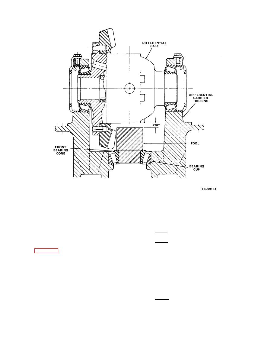
Figure 3-13. Measuring for bearing shims. |
|
||
| ||||||||||
|
|
 TM 10-3930-631-34
Figure 3-13. Measuring for bearing shims.
(9) Install pins (24) in flanged half and aline
amount of shims required to locate the theoretical
holes in ring gear with pins. Install ring gear on
exact pinion. Refer to the following example:
flanged half and secure with screws (22). Tighten
2.495 (one-half of differential case outside diameter)
screws securely.
+ .220 (distance from (12) above)
2.715 total
(10)Measure outside diameter of differential
-2.650 (theoretical setting distance)
case at center of case, not ring gear pilot.
.065 thickness of shims required to locate an exact
(11)Install differential case in carrier as
pinion (no manufacturing tolerance)
shown in figure 3-13.
Note
Note
All pinions are etched with manufacturing
Bearing caps do not have to be in place.
tolerances.
(12)Measure and record the distance
(14)If pinion is a plus .005 inches (etched
between the outside of the differential case and the
2.655) the .005 inches has already been added to
face of the tool.
the theoretical setting distance, therefore the amount
(13)Add one-half the outside diameter of the
of shims required is found as follows:
case to the dimension taken in (12) above. Subtract
2.715 total
2.650 inches from the total to get the
.-2.655 (theoretical setting plus .005)
.060 thickness of shims required
3-13
|
|
Privacy Statement - Press Release - Copyright Information. - Contact Us |
