 |
|||
|
|
|||
|
Page Title:
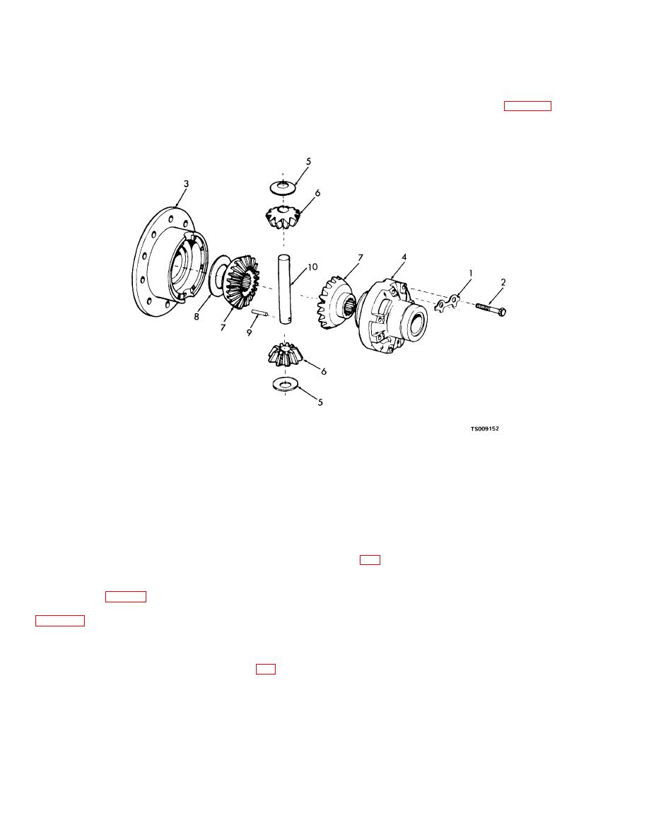
Figure 3-11. Differential assembly, exploded view. |
|
||
| ||||||||||
|
|
 TM 10-3930-631-34
(22)and remove ring gear from differential case.
suitable bearing puller remove bearing cones (33)
Remove pins (24) from ring gear.
from differential cases.
(3) Remove bearing cups (32).
Note
(4) Remove locks (1, fig. 3-11) and screws
Ring gear and pinion (23) are a matched set.
(2) securing- case halves (3 and 4) together and
(2)
Remove adjusting nuts (31) and
separate case halves.
using a
1.
Lock
6. Pinion gear
2.
Screw
7. Bevel gear
3.
Flanged case
8. Thrust washer
4.
Plain case
9. Dowel pin
5.
Thrust washer
10. Pinion shaft
Figure 3-11. Differential assembly, exploded view.
Note
Place carrier in and arbor press and press pinion
One case half is flanged and the other plain.
(23) from carrier. Drive bearing cone (19) and cups
Case halves must be marked for proper
(20 and 27) from carrier using a brass drift. Pull
assembly (fig. 3-9).
bearing cone (26) from pinion gear and remove
(5) Remove pinion gear thrust washers (5,
shims (25). Tag and record quantity of shims.
c. Cleaning, Inspection and Repair.
(10). Remove pin (9).
(1) Clean all parts in cleaning compound,
(6) Remove bevel gears (7) and thrust
washers (8) and remove pinion shaft (10).
(7) Straighten tabs on tab washer (17, fig.
3-11
|
|
Privacy Statement - Press Release - Copyright Information. - Contact Us |
