 |
|||
|
|
|||
|
|
|||
| ||||||||||
|
|
 TM 10-3930-631-34
b. Installation.
(1) Using a hoist, place carriage frame and side
shifter in position below inner mast. Aline bearings with
channels in inner mast.
(2) Using the hoist, raise and lower the carriage
in the inner mast several times to check for free
movement throughout entire range of travel. If bearings
bind, refer to paragraph 7-10 and shim bearings for
proper clearance.
(3) When carriage frame moves freely secure
chains to frame. Before releasing the hoist check t( see
that chains are secure at the cylinder cluster and running
evenly, with no twists, through the crosshead bearings.
Adjust chain length for even lift, if necessary. Refer to
TM10- 3930-631-12.
(4) Install screws and spacer on rear of
carriage supports.
(5) Remove blocks and lower inner mast to
floor, using a suitable hoist.
(6) Remove plugs and caps and connect
hydraulic hoses to side shift cylinder and swivel block on
carriage.
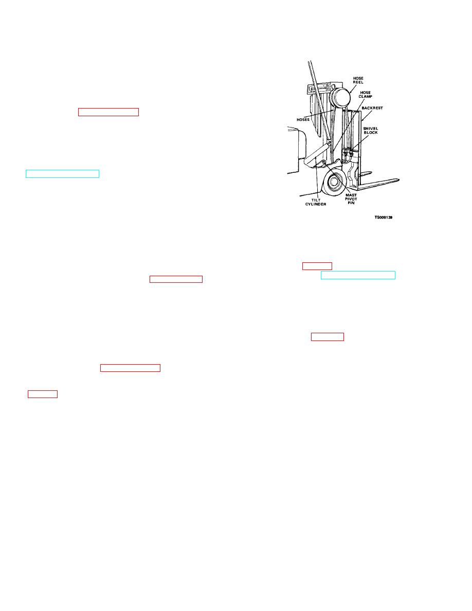
Figure 2-6. Side shift hoses and hose reel.
(7) Connect battery receptacle and operate
mast assembly through entire range of travel.
(3) Remove nuts, screws and lock washers and
(8) Check carriage movement for sideplay and
remove clamps (fig. 2-6) and hoses from outer mast.
binding. Check operation of side shift.
(4) Refer to TM10-3930-631-12 and disconnect
(9) If bearings bind, refer to paragraph 7-15e.
tilt cylinders from mast.
(7) to shim bearings and provide proper clearance.
(5) Disconnect hydraulic hose from flow
(10)Lower the carriage to lowest point of travel
regulator at rear of mast. Plug hose and hydraulic fitting
and check the distance from the lowest horizontal fork
to prevent entrance of foreign material.
3
1
support to the floor. Adjust to bring support to 2 /4 - 3 /4
(6) Connect a hoist to the mast assembly and
inches (69. 8 - 82. 5 mm) from floor. Refer to TM10-
raise the mast assembly enough to remove weight from
3930-631-12 for adjustment procedures.
mast pivot pin (fig. 2-6). Remove screws and lock
(11)Install carriage forks and lock in position.
washers and remove pivot pins.
2-15. Mast Assembly
a. Removal.
(1) Refer to paragraph 2-14 and remove side
shift carriage from mast assembly.
(2) Disconnect hydraulic hoses from hose reel
cap ends of hoses and fittings in junction block and hose
reel to prevent entrance of foreign matter.
2-12
|
|
Privacy Statement - Press Release - Copyright Information. - Contact Us |
