 |
|||
|
|
|||
|
|
|||
| ||||||||||
|
|
 TM 10-3930-631-34
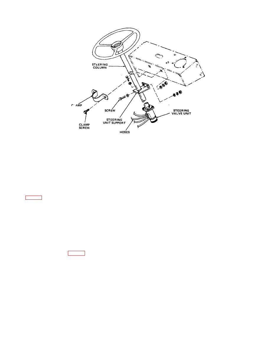
Figure 2-3. Steering valve unit.
(3) Disconnect horn button wire at horn.
(4) Connect horn button wire to horn terminals .
(4) Remove two screws securing clamp (fig. 2-
(5) Remove plugs from steering unit and hoses.
3) to instrument panel frame and remove clamp.
Check tags and connect hoses to steering unit.
Remove two screws securing shift lever clamp to
(6) Connect battery receptacle.
steering column and remove clamp.
(7) Check hydraulic reservoir and add oil if
(5) Remove two screws securing steering unit
necessary.
support to frame.
2-13. Hydraulic Pump and Motor
(6) Remove two screws securing steering valve
a. Removal.
unit (fig. 2-3) to stationary bracket.
CAUTION
(7) Lift steering valve unit, with steering wheel
Before proceeding with removal of the hydraulic
and shaft attached, carefully up and out of truck. Place
pump and motor, disconnect the battery
unit on a clean work surface.
receptacle and discharge the capacitors.
b. Installation.
(1) Raise truck, using a suitable hoist,
(1) Lift steering valve unit into position and support it
sufficiently to gain access to hydraulic pump. Block truck
against stationary bracket. Install screws and lock
securely.
washers to secure unit to stationary bracket.
(2) Remove the drip pan from beneath truck.
(2) Position support against frame and install
Remove floor and toe plates.
screws, lock washers, flat washers and nuts to support
(3) Remove the drain plug from the hydraulic oil
steering unit.
reservoir and drain the hydraulic oil into a clean container
(3) Install clamp (fig. 2-3) around steering post
of suitable size.
and secure clamp to instrument panel frame with screws
and washers. Install shift lever clamp.
2-8
|
|
Privacy Statement - Press Release - Copyright Information. - Contact Us |
