 |
|||
|
|
|||
|
Page Title:
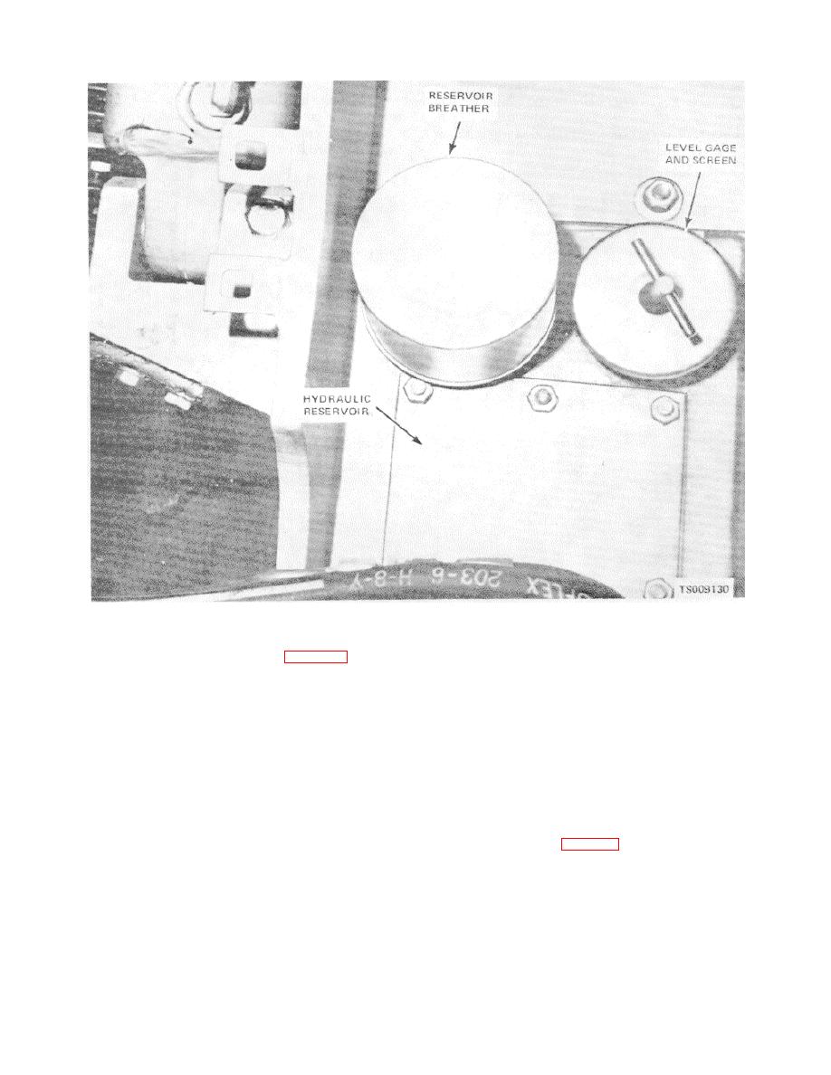
Figure 4-46. Hydraulic reservoir. |
|
||
| ||||||||||
|
|
 TM 10-3930-631-12
Figure 4-46. Hydraulic reservoir.
b. Installation.
(2) Remove breather (fig. 4-46) from
hydraulic reservoir.
(1) Install screen in hydraulic reservoir gage
(3) Check breather for damage. If breather
filler pipe.
is damaged, replace breather.
(2) Install hydraulic reservoir gage (fig. 4-
b. Installation.
46) in reservoir.
(1) Install breather in place on reservoir.
(3) Install floor and toe plates.
(2) Install floor and toe plates.
4-61. Hydraulic Oil Filter
a. General. The hydraulic oil filter is mounted on a
4-60. Hydraulic Reservoir Inlet Screen
a. Removal.
bracket on the frame below the seat. All return oil from
(1) Remove floor and toe plates to gain
the hydraulic system and steering system flows through
access to reservoir.
the filter before returning to the reservoir. A filter
(2) Remove hydraulic reservoir gage (fig. 4-
element indicator (fig. 4-48) is mounted on a bracket
46) from reservoir.
above the filter. Pressure of the oil passing through the
(3) Remove screen from below gage.
filter registers on the indicator. A white indicating line in
(4) Clean screen in cleaning compound,
the indicator is moved by the pressure. If the
solvent (Fed. Spec. P-D-680) and dry thoroughly.
4-53
|
|
Privacy Statement - Press Release - Copyright Information. - Contact Us |
