 |
|||
|
|
|||
|
Page Title:
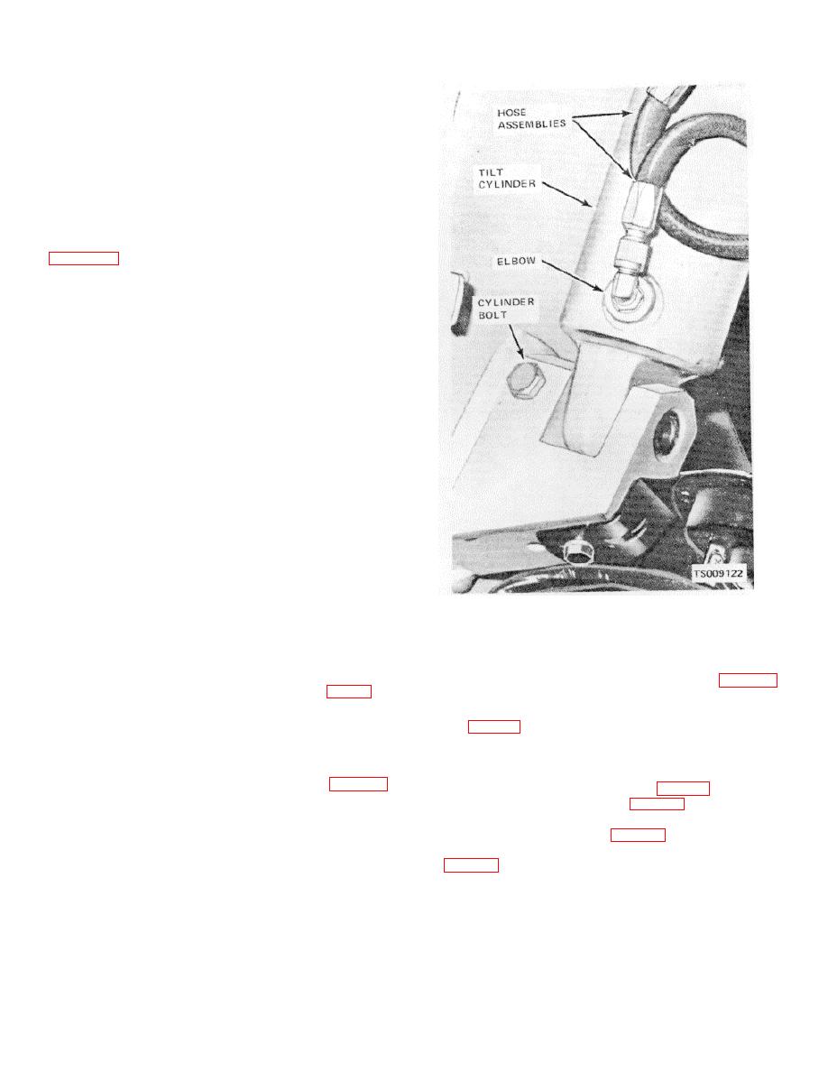
Figure 4-38. Tilt cylinder, installed view. |
|
||
| ||||||||||
|
|
 TM 10-3930-631-12
(2) Loosen switch mounting screws and
move switch in or out as required. Switch rollers should
just touch grooves in actuators. Tighten switch mounting
screws.
(3)
Move control levers and check
adjustment.
(4) Connect battery receptacle and check
operation.
Pump should operate before cylinders
extend.
Switch Replacement.
If switch requires
d.
replacement, disconnect battery receptacle and refer to
(1) Disconnect wires from switch.
(2) Remove two mounting screws and
remove switch.
(3) Install new switch and secure with
mounting screws.
(4) Connect wires to switch.
(5) Check and adjust switch (c above) to
assure proper operation.
(6) Connect battery receptacle.
e. Control Lever Replacement. Refer to figure 4-
36 and replace control levers as follows:
(1) To replace lever knobs, remove knob
from lever.
(2) To replace lever, remove cotter pin and
yoke pin to disconnect lever from yoke.
(3) Remove retaining rings and remove
lever shaft from brackets and levers.
(4) Remove levers and spacing washers.
(5) Install new levers, with shaft through
brackets, levers and spacing washers. Secure shaft with
retaining rings.
(6) Connect yokes to levers with screws and
self-locking nuts.
4-54. Tilt Cylinder
Figure 4-38. Tilt cylinder, installed view.
a. General. Two tilt cylinders, one on each side of
the frame, provide power to tilt the mast.
(4) Support cylinder with a block of wood.
b. Removal. Remove the tilt cylinder as follows:
Remove cotter pins and remove yoke pin (fig. 4-39)
(1) Operate the tilt control lever (fig. 2-1) to
from yoke and mast.
tilt the mast forward. Connect a chain hoist to the mast
(5) Remove cylinder bolt and self-locking
to hold it in a forward position.
nut (fig. 4-38) securing rear of cylinder to frame.
(2) Remove floor and toe plates. Remove
(6) Remove cylinder from truck.
drip pan from underside of truck. Inspect tilt cylinders for
c. Installation. Install tilt cylinder in truck as
leaks and damage. Replace cylinders if necessary.
follows:
(3) Disconnect hose assemblies (fig. 4-38)
(1) Install tilt cylinder (fig. 4-38) in position
from elbows in cylinder. Plug hose and cylinder ports.
on truck. Install cylinder blot (fig. 4-38) through frame
and cylinder and secure with self-locking nut.
(2) Install pin (fig. 4-39) through mast and
yoke at front of cylinder. Secure pin with two cotter pins
4-46
|
|
Privacy Statement - Press Release - Copyright Information. - Contact Us |
