 |
|||
|
|
|||
|
Page Title:
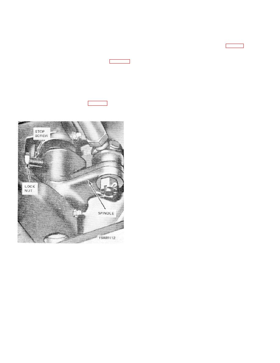
Figure 4-28. Spindle stop screw adjustment. |
|
||
| ||||||||||
|
|
 TM 10-3930-631-12
d. Drag Link Adjustment.
(7) Loosen nut (7) and adjust length of rods
by turning ball socket in or out on tube to bring both
(1) Position the rear wheel straight ahead
measurements equal. Torque nut (7) to 50 to 70 foot-
and parallel with the frame.
pounds to secure adjustment.
(2) Remove cotter pin (2, fig. 4-29) from the
(8) Install ball socket (9) on spindle and
end of drag link (3) and loosen adjusting plug (1).
secure with boot (10), nut (11) and cotter pin (12).
(3) Lift drag link from ball stud on pivot arm
(10).
secured by lock nuts extend through the axle and
prevent extreme inward pivoting of spindles and to
prevent piston from bottoming in steering cylinder.
(1) Turn master switch on the turn wheels
full right and full left. Measure clearance between tire
and steering axle housing at both wheels. Clearance
should be a minimum of one-half inch.
(2) Loosen lock nut (fig. 4-28) and adjust
stop screw to stop spindle with proper clearance. Hold
stop screw and tighten lock nut to secure adjustment.
Figure 4-28. Spindle stop screw adjustment.
4-34
|
|
Privacy Statement - Press Release - Copyright Information. - Contact Us |
