 |
|||
|
|
|||
|
|
|||
| ||||||||||
|
|
 TM 10-3930-631-12
1.
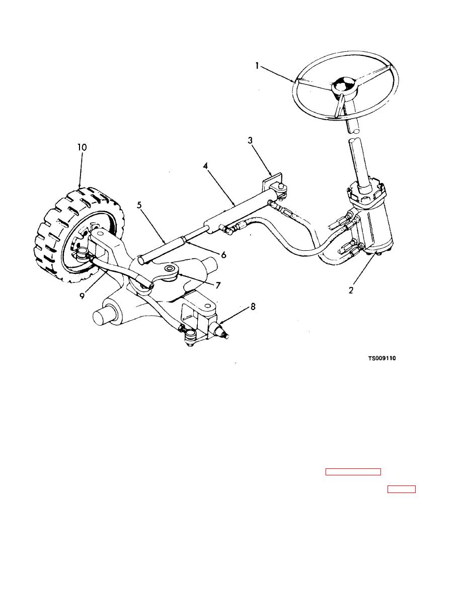
Steering wheel
6. Lock nut
2.
lower steering unit
7. Pivot arm
3.
Cylinder anchor
8. Spindle
4.
Steering cylinder
9. Tie rod
5.
I)rag link
10 Rear wheel
Figure 4-26. Steering system.
b. A separate electric motor driven pump supplies
turns the wheels in the direction desired.
hydraulic oil under pressure to the steering unit (2, fig. 4-
26). Rotation of the steering wheel (1) allows oil
4-39. Steering Wheel
pressure to flow to the steering cylinder (4). The cylinder
a. Removal.
piston moves under the pressure. Attached to the piston
(1) Refer to paragraph 4-25 and remove the
is a rod which is in turn connected to the drag link (5).
horn button.
Movement of the rod and drag link rotates the pivot arm
(2) Remove lock wire (7, fig. 4-9) and
(7). The two tie rods (9) are connected to the pivot arm
screws (8) and remove base plate (9).
and wheel spindles (8). The tie rods move the spindles
which mount the wheels (10). Movement of the spindles
4-32
|
|
Privacy Statement - Press Release - Copyright Information. - Contact Us |
