 |
|||
|
|
|||
|
Page Title:
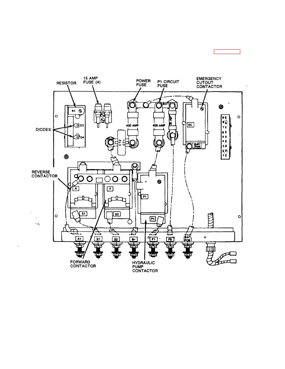
Figure 4-11. Contactor box, installed view. |
|
||
| ||||||||||
|
|
 TM 10-3930-631-12
made of a silver alloy. The contacts may have to be
4-28. Relay Contacts
dressed or replaced to insure proper operation. Remove
a. General. Four contactor assemblies serve to
cover from contactor box to gain access to the
connect components into the circuit. The contactors are
contactors.
mounted in the contactor box at the front of the battery
b. Removal. Refer to figure 4-11 and remove
compartment below the seat. The contactors operate
contacts from contactor armatures.
the hydraulic pump motor, forward and reverse motion
(drive motor) and the emergency cutout. Contacts are
1.
TO REMOVE CONTACT POINTS FROM FORWARD, REVERSE AND HYDRAULIC PUMP CONTACTORS,
REMOVE SCREW AND LOCK WASHER.
2.
TO REMOVE POINTS FROM EMERGENCY CUTOUT CONTACTOR, REMOVE NUT AND LOC K WASHER.'
Figure 4-11. Contactor box, installed view.
Change 2 4-16
|
|
Privacy Statement - Press Release - Copyright Information. - Contact Us |
