 |
|||
|
|
|||
|
Page Title:
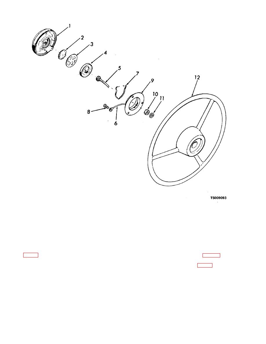
Figure 4-9. Horn button, exploded view |
|
||
| ||||||||||
|
|
 TM 10-3930-631-12
1.
Cover
7.
Lock wire
2.
Disk
8.
Screw
3.
Contact spring
9.
Base plate
4.
Contact cup
10.
Nut
5.
Wire
11.
Lock washer
6.
Ground wire
12.
Steering wheel
Figure 4-9. Horn button, exploded view.
(3) Installation. Connect wires to base plate
4-26. Battery and Receptacle
(9, fig. 4-9) and contact cup. Install cup (4), spring (3)
a. General. The battery (fig. 4-10) is mounted in
and disk (2) in wheel. Install cover (1) and twist
a compartment below and to the rear of the operator's
clockwise to engage lugs.
seat. The battery receptacle (fig. 4-4) is mounted on the
left side of the battery compartment.
4-13
|
|
Privacy Statement - Press Release - Copyright Information. - Contact Us |
