 |
|||
|
|
|||
|
Page Title:
CHAPTER 12 TRANSMISSION REPAIR INSTRUCTIONS |
|
||
| ||||||||||
|
|
 TM 10-3930-630-34
CHAPTER 12
TRANSMISSION REPAIR INSTRUCTIONS
Section I. TRANSMISSION CONTROLS
connected to the transmission forward and reverse
12-1. Description
plunger with a shift rod and clevis.
d. The inching pedal operates the inching valve
of three major components: the torque converter, a
through a pin and screw attached to the valve plunger.
hydraulically actuated clutch pack and a single speed,
constant mesh transmission.
b. A single lever type shift control is mounted on
12-2.
Transmission
Controls,
Removal
and
the steering column to control the direction of travel
Disassembly
through a control valve mounted on the transmission
a. Removal.
housing.
(1) Refer to TM 10-3930-630-12 and remove
c. The transmission is controlled through a linkage
floor and toe plates.
extending from the bottom of the control column. A
(2) Removal of the transmission controls is
lever at the end of the column is
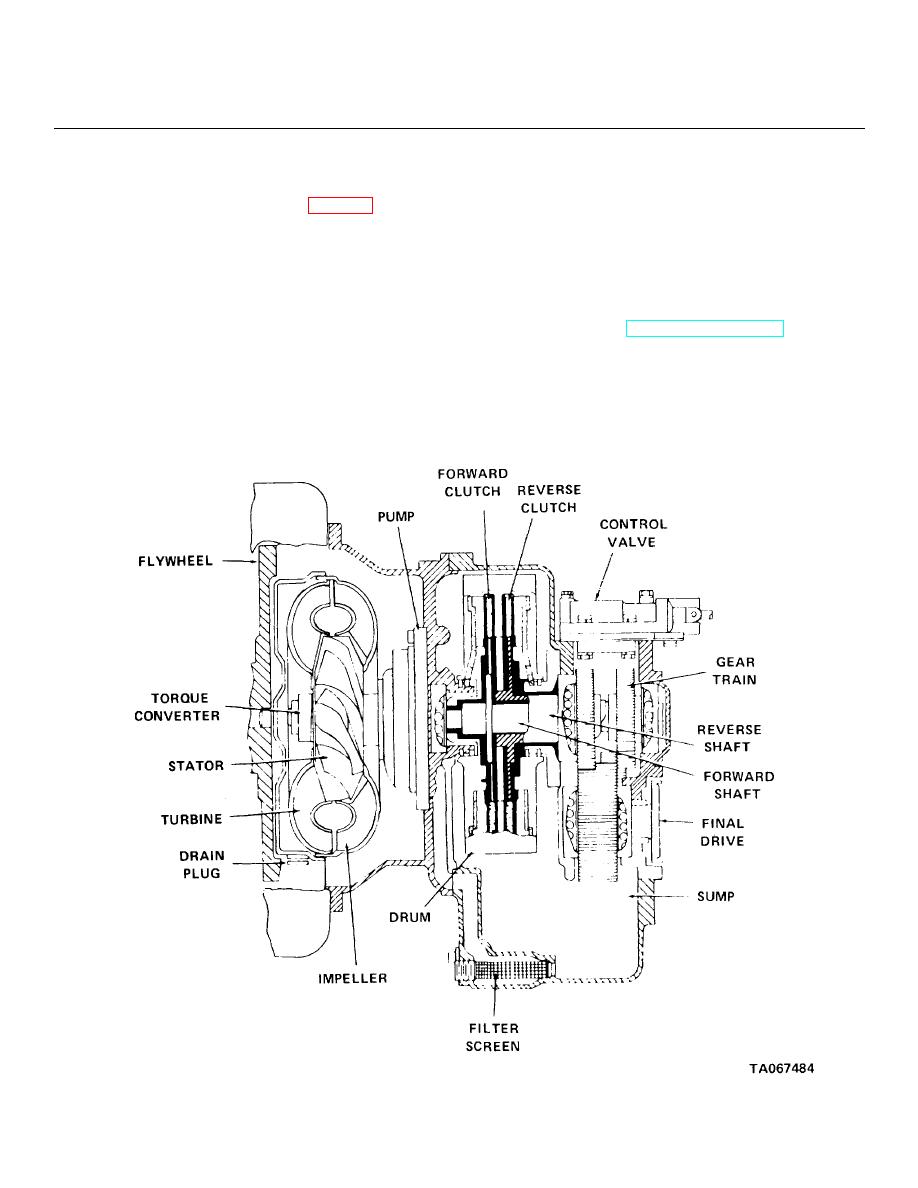
Figure 12-1. Transmission, cutaway view.
12-1
|
|
Privacy Statement - Press Release - Copyright Information. - Contact Us |
