 |
|||
|
|
|||
|
Page Title:
Valve Mechanism, Reassembly and Installation |
|
||
| ||||||||||
|
|
 TM 10-3930-630-34
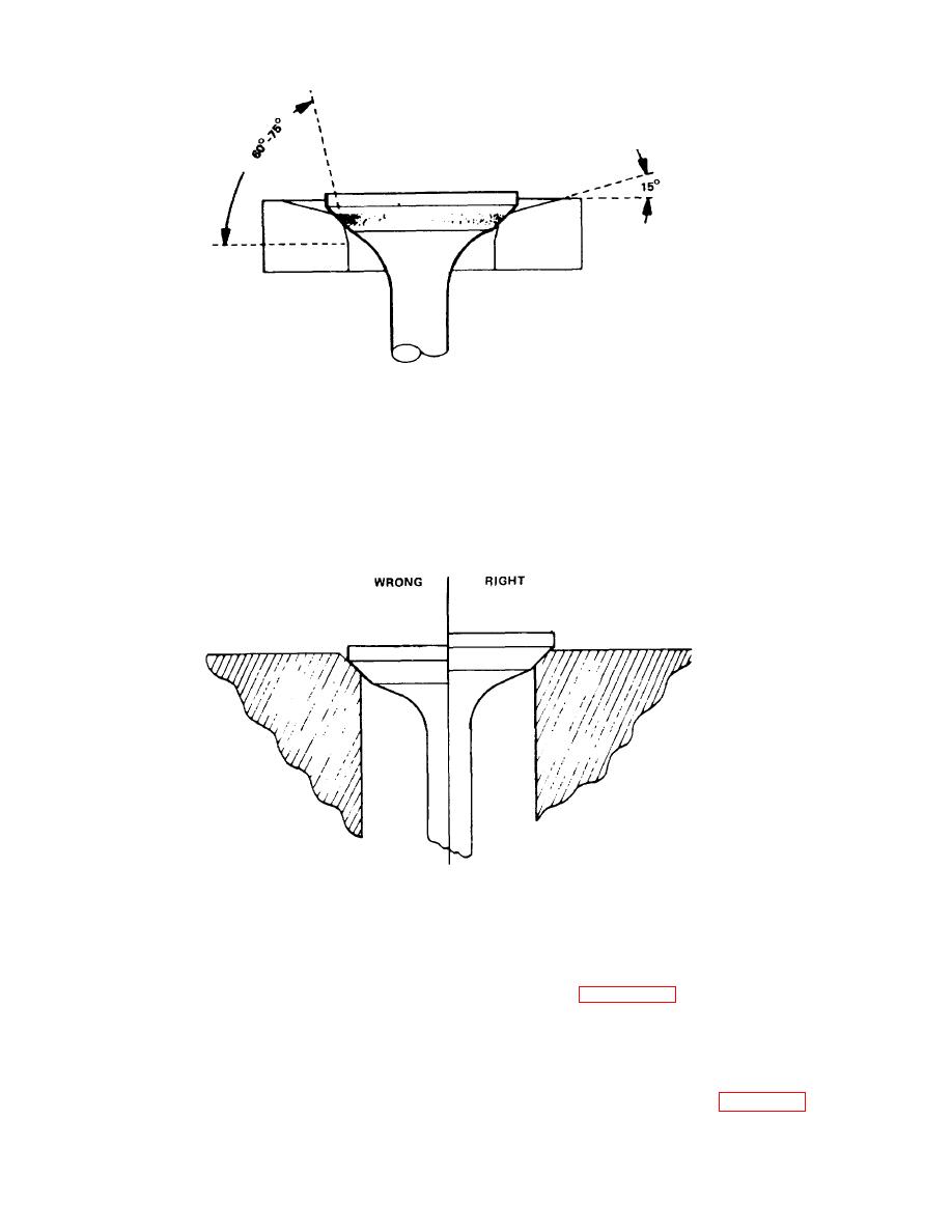
TA067449
Figure 11-9. Method of grinding valve seats.
tolerances.
(2) Maximum wear limit is 0.9985 inch (25.36
m. Inspect tappets for wear and damage.
mm).
n. Check tappets as follows:
(3) Tappet bore in block should be 1.0000
(1) Outside diameter of tappet should be
inch (25.4 mm). Maximum wear limit is 1.0050 inch
0.9995 to 0.9990 inch (25.38 to 25.37 mm).
(25.52 mm)
TA067450
Figure 11-10. Valve position in cylinder block.
guides by pressing into block. Press guides in from
11-5.
Valve
Mechanism,
Reassembly
and
combustion side.
Installation
d. Press valve guides into place to the distances
NOTE
shown on figure 11-11. Both valve guides should be
The valve mechanism is reassembled during the
1.4062 inch (35.71 mm) from face of block.
installation procedure.
e. Check inside diameter of valve guides after
a. Check length of valve guide. Length should be
installation and ream to inside diameter of 0.3432 to
2.3125 inch (58.7 mm)
0.3422 (8.74 to 8.69 mm) if necessary. Clean guides
b. Check outside diameter.
Outside diameter
and block thoroughly after reaming.
should be 0.6675 to 0.6565 inch (16.9 to 16.6 mm).
f. Install valve tappets (9, fig. 11-2A) in cylinder
c. Use a suitable pressing tool and install valve
11-6
|
|
Privacy Statement - Press Release - Copyright Information. - Contact Us |
