 |
|||
|
|
|||
|
Page Title:
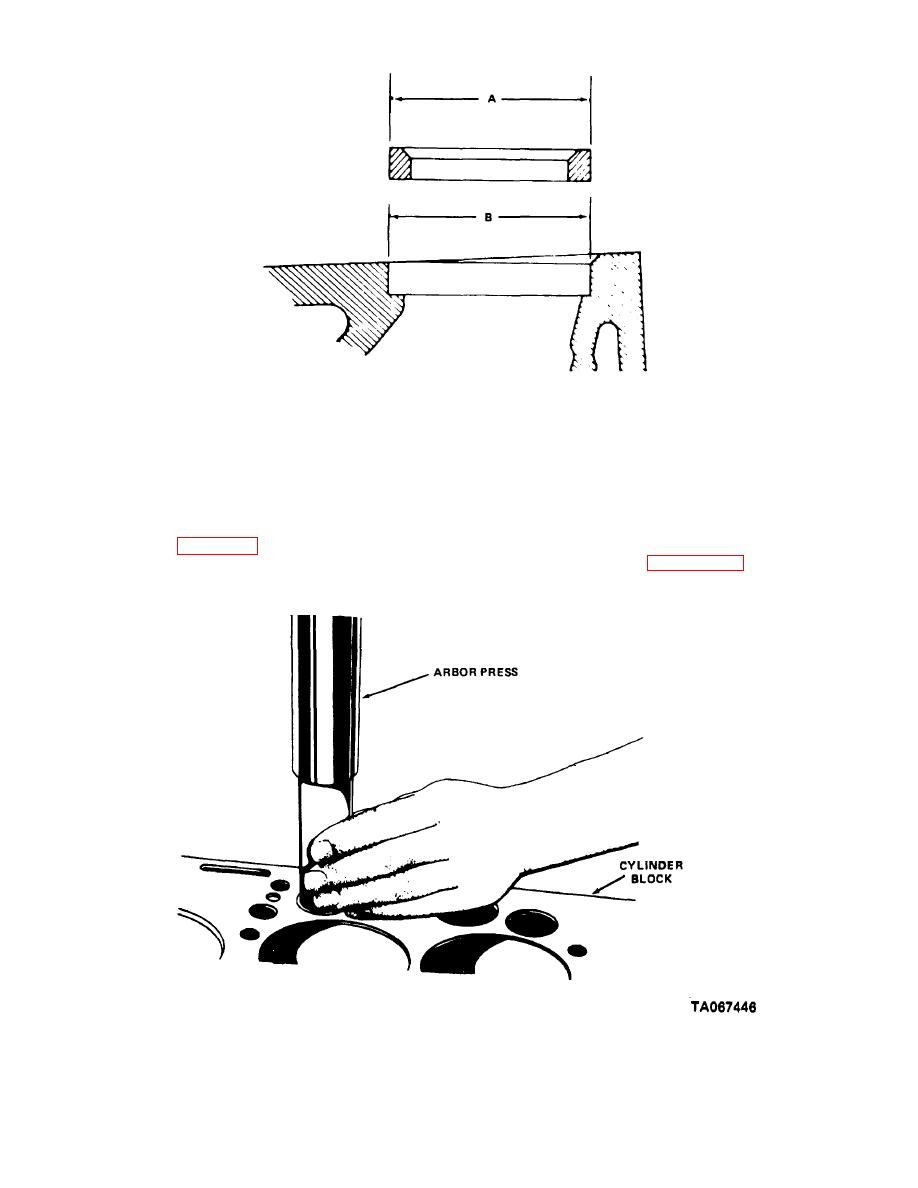
Figure 11-5. Insert and counter bore dimensions. |
|
||
| ||||||||||
|
|
 TM 10-3930-630-34
A. O.D. OF INSERT
1.3485-1.3475 INCH
B. I.D. OF COUNTEBORE
1 3445-1.3435 INCH
PRESS FIT
0.003-0.005 INCH
TA067445
Figure 11-5. Insert and counterbore dimensions.
Intake valve angle is 30 degrees. Exhaust valve angle
(8) a piloted driver and press the insert in
is 45 degrees.
place as shown on figure 11-6.
(2) Refer to figure 11-7 for valve head
i. Grind valves and valve seats as follows:
thickness.
(1) Reface valves using a valve grinding tool.
Figure 11-6. Valve seat insert installation.
11-4
|
|
Privacy Statement - Press Release - Copyright Information. - Contact Us |
