 |
|||
|
|
|||
|
Page Title:
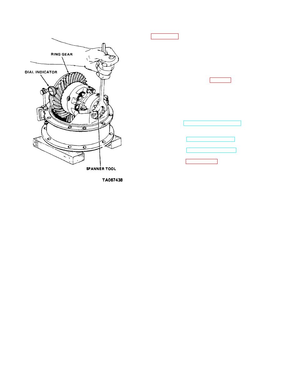
Figure 10-8. Adjusting differential backlash. |
|
||
| ||||||||||
|
|
 TM 10-3930-630-34
inch (0.78 to 1.57 mm) from the top of the tooth and
continue downward to an equivalent distance from the
bottom of the tooth.
NOTE
Do not be concerned with the
amount of paint removed. This will
vary with load applied.
(6) Tighten screws (6, fig. 10-6) securing bearing
caps (7) and lock with lock wire (5). Secure adjusting
nuts with locks (3), lock washers (2) and screws (1).
(7) Position a new gasket on mounting flange of
axle housing and coat with a leak proof adhesive.
(8) Align carrier housing stud holes with studs of
axle housing and install carrier on axle housing. Secure
with selflocking screws and nuts.
(9)
Refer to TM 10-3930-630-12 and connect
parking brake cable at brake drum lever and connect
hydraulic lines.
(10) Refer to LO 10-3930-630-12 and replace drin
plug and service the differential assembly.
(11) Refer to TM 10-3930-630-12 and install axle
shafts and drive shaft.
(12) Refer to paragraph 7-4 and install drive wheels.
Figure 10-8. Adjusting differential backlash.
10-9
|
|
Privacy Statement - Press Release - Copyright Information. - Contact Us |
