 |
|||
|
|
|||
|
|
|||
| ||||||||||
|
|
 TM 10-3930-630-34
(3) Press bearing cones (4) and cups (5) on
threaded holes for damage. Repair damaged threads if
shaft (8).
possible.
(4) Secure bearings with washers (2 and 3)
f. Inspect cover for cracks and damage. Discard
and nut (1). Lock nut by bending tabs of washer (2).
cover gasket.
(5) Install new seal (11) in housing (21).
g. Check locating pin for secure mounting and
Install new gasket (19) and install cover (18). Secure
damage.
cover with screws (15 and 16) and lock washers (17).
h. Replace all unserviceable parts.
b. Installation.
(1) Refer to paragraph 94 and install the service
10-12. Drive Axle and Axle Shaft, Reassembly and
brakes.
Installation
(2) Refer to TM 10-3930-630-12 and install the axle
a. Reassembly.
shaft, spindle, and brake dust shield.
(1) Lubricate bearing cones (4, fig. 10-4) and
(3) Refer to paragraph 7-4 and install the drive
cup (5) with grease per LO 10-3930-630-12.
wheel on the truck.
(2) Install cap (7) and new seal (6) on shaft
(4) Refer to paragraph 2-30 and install drive axle on
(8).
the truck.
Section IV. DIFFERENTIAL
(8) Remove screws (1, fig.
10-6), lock
10-13. Description
washers (2) and bearing locks (3). Remove adjusting
The differential mounted on the rear of the drive axle, is
nuts (4) from bearing caps and housing. Remove lock
connected to the drive shaft. Rotation of the drive shaft
wire (5) and screws (6) securing bearing caps (7) to
rotates the differential. The axle shafts are splined to
housing. Remove bearing caps (7).
the differential. As they rotate the ends of the axle
shafts rotate in the bull gears. The bull gears and
wheels are mounted at the outer ends of the axle and
rotate to drive the truck.
10-14. Differential, Removal and Disassembly
a. Removal.
(1) Refer to paragraph 7-2 and remove the
drive wheels.
Refer to TM 10-3930-630-12 and
disconnect drive shaft from differential.
(2) Refer to LO 10-3930-630-12 and drain the
differential housing.
(3) Refer to TM 10-3930-630-12 and remove
the parking brake cable at the brake actuating lever, and
disconnect and plug the hydraulic brake lines.
(4) Using a suitable support for the
differential remove the screws which mount the carrier
and differential to the axle housing.
(5) Carefully remove carrier and differential
assembly from the axle housing and place on a suitable
work bench.
NOTE
It may be necessary to lightly tap the
carrier housing in order to free it
from seal.
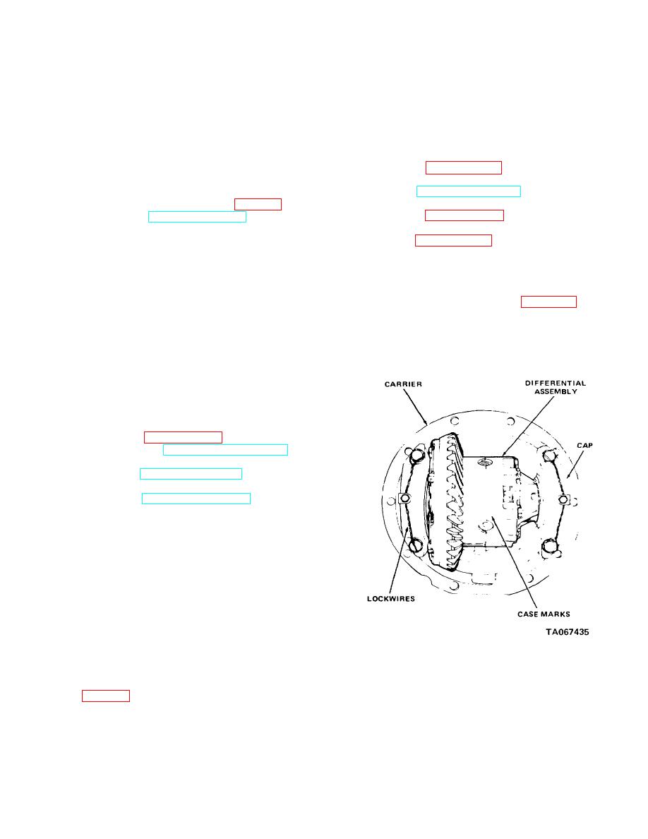
Figure 10-5. Differential, removal and installation.
(6) Remove and discard gasket between
carrier housing and axle housing
10-15. Differential, Cleaning, Inspection and Repair
(7) Match mark bearing caps and differential
a. Clean all parts with cleaning solvent, (Fed.
housing (fig. 10-5) to aid in proper alignment during
Spec.P-D-680).
reassembly
b. Inspect bearings for damage and excessive
wear. Replace if damage is noted.
10-6
|
|
Privacy Statement - Press Release - Copyright Information. - Contact Us |
