 |
|||
|
|
|||
|
Page Title:
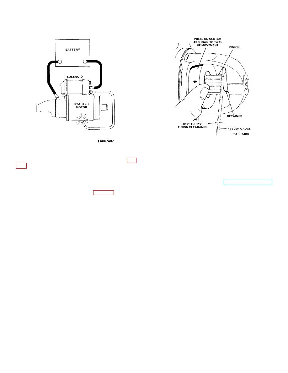
Figure 4-10. Test circuit for pinion clearance check. |
|
||
| ||||||||||
|
|
 TM 10-3930-630-34
Figure 4-10. Test circuit for pinion clearance check.
Figure 4-11. Measuring pinion clearance.
(3) Momentarily touch a jumper lead (fig.
(6) Clearance must be 0.010 to 0.140
inch (0.25 to 3.5 mm). If clearance is not within limits,
(4) This will shift drive assembly pinion
disassemble starter and replace drive assembly and/or
into cranking position. Push pinion back toward
commutator to eliminate slack in drive assembly.
c. Installation. Refer to TM 10-3930-630-12
(5) Measure the distance between pinion
and
install
starter
on
engine.
and pinion stop with a feeler gage (fig. 4-11) to obtain
pinion clearance.
4-8
|
|
Privacy Statement - Press Release - Copyright Information. - Contact Us |
