 |
|||
|
|
|||
|
Page Title:
Section II. MAINTENANCE ALLOCATION CHART |
|
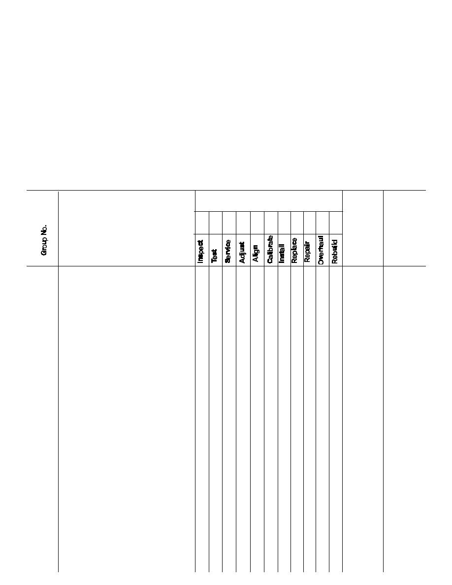
||
| ||||||||||
|
|
 TM 10-3930-630-12
d. Column 4. Tools and Equipment. This column is
lowest level of maintenance authorized to use the
special tools or test equipment.
provided for referencing by code the special tools and
c. Nomenclature. This column lists the name or
test equipment. (section III) required to perform the
identification of the tools or test equipment.
maintenance functions (section II).
d. Tool Number. This column lists the
e. Column 5. Remarks. This column is provided for
manufacturer's code and part number, or national stock
referencing by code the remarks (section IV) pertinent to
number of tools and test equipment.
the maintenance functions.
B-4.
Explanation of Columns in Section IV
B-3.
Explanation of Columns in Section III
a. Reference Code. This column consists of two
a. Reference Code. This column consists of a
letters separated by a dash, entered from column 5,
number and a letter separated by a dash entered from
section II. The first letter references the remark and the
column 4 on the MAC. The number references the
second letter references a maintenance function,
special tools and test equipment requirements and the
column 3, A through K, to which the remark applies.
letter represents the specific maintenance function the
b. Remarks. This column lists information perti-
item is to be used with. The letter is representative of
nent to the maintenance function being performed,
columns A through K on the MAC.
b. Maintenance Level. This column shows the
as indicated on the MAC. section II.
Section II. MAINTENANCE ALLOCATION CHART
(1)
(2)
(3)
(4)
(5)
Assembly Group
Maintenance functions
Tools and Remarks
equipment
A
B
C
D
E
F
G
H
I
JK
01
OVERHEAD GUARD AND
O
O
PANEL
0.2
1.0
02
OPERATORS SEAT
O
O
0.1
0.5
0.2
0.5
03
BODY PANEL AND HOODS
O
OO
0.2
0.5 1.0
04
INSTRUMENT PANEL AND
C
D
O
INSTRUMENTS
0.2
0.3
1.0
05
MAST ASSEMBLY
O
OOO
OF
0.2
0.4 0.2 0.5
0.5 1.0
06
HYDRAULIC LIFT
COMPONENTS:
Lines and Fittings
OO
O
0.3 0.4
0.5
Lift Chains
O
O
O
0.1
0.4
0.5
Lift Cylinder
O
OF
0.4
0.5 1.0
Tilt Cylinder
O
O
F
0.4
0.5 1.0
Control Valve
FF
1.0 2.0
Hydraulic Tank and Oil
O
OF
Filter
0.2
1.0 1.0
Hydraulic Pump
FF
FF
0.2 0.5
1.0 2.5
07
ELECTRICAL SYSTEM:
Batteries and Cables
O
OO
02 0.5
0.4 0.5
Lights, Horn and Wiring
O
OO
0.4
0.5 0.5
O
O
OF
0.5
0.5 2.0
Starting Motor
O
OF
0.5
0.5 4.0
Distributor
OO
OO
0.5 0.5
0.5 1.0
Spark Plugs
OO
O
0.5 0.2
0.5
B-2
|
|
Privacy Statement - Press Release - Copyright Information. - Contact Us |
