 |
|||
|
|
|||
|
|
|||
| ||||||||||
|
|
 TM 10-3930-630-12
TA034848
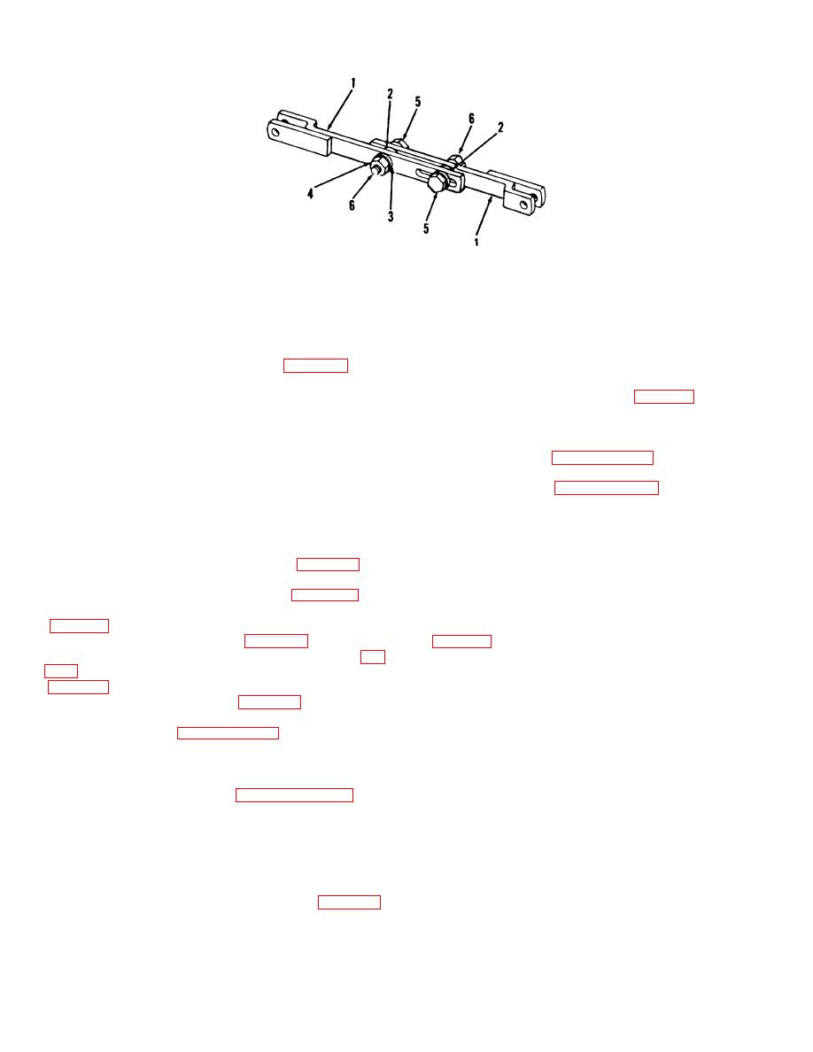
1 Slide assemblies
4 Lockwasher
2 Nylon washer
5 Screw
3 Washer
6 Nut
Figure 4-73. Brake adjuster, disassembly and assembly
(1) Install slide assemblies (1, Fig. 4-73) with
wheel cylinder.
nylon washers (2) between slides.
c. Installation.
(2) Secure slides with screws (5), nuts (6) and
(1) Install wheel cylinder (Fig. 4-72) on backing
washers (3 and 4). Tighten only finger tight.
plate.
(3) Move slides along slot until center-to-center
(2) Secure wheel cylinder to backing plate with
distance of holes in ends of slides is 5.15 inches (133.5
two screws (Fig. 4.74).
mm). Tighten screws (5) to a torque of 14 to 16 pound-
(3) Refer to paragraph 4-88 and install service
inches (1.58 to 1.80 N-m).
brake shoes and backing plate.
(4) Hold screws in position and tighten nuts (6)
(4) Refer to paragraph 4-85 and install front
to a torque of 29 pound-inches (3.2 N-m).
wheels.
(5) Check slip resistance of slide assemblies.
(5) Refer to & below and bleed brake system.
Resistance should be 250 to 300 pounds (113 to 135
kg).
the system has been drained and refilled or a part-has
(6) Install wheel cylinder links (Fig. 4-72) on
been disconnected or replaced the system must be bled.
bottom of brake shoes and secure with pins.
(1) Remove filler cap from master cylinder and
(7) Install adjuster assembly (Fig. 4-72) on
fill to proper level (0.375 to 0.50 inch (9.5 to 12.7 mm)
brake shoes and secure to brake shoes with spring pins
from top).
(2) Connect a bleeder hose to bleeder screw
(8) Install brake shoes (Fig. 4-72) on backing
plate, with links installed in ends of wheel cylinder (fig.
in a glass jar filled with brake fluid.
(3) Open bleeder screw one turn.
(4) Slowly depress brake pedal to end of travel
(9) Install dust shield (Fig. 4-71) on axle and
and release pedal Repeat several times. Observe hose
secure with four screws and lockwashers.
in jar and repeat pumping of brake pedal until no
(10) Refer to paragraph 4-85 and install front
bubbles escape from hose. Hold pedal at bottom of
drive wheels.
travel and close bleeder screw to keep additional air
from entering system.
4-89. Service Brake Wheel Cylinder
a. Inspection.
NOTE
Refer to paragraph 4-88 and
remove front wheel and dust shield. Inspect wheel
cylinder for leaks, damage and proper link movement.
While pumping pedal check fluid level in master
Replace wheel cylinder if necessary.
cylinder. Add fluid to keep cylinder close to full
b. Removal
at all times.
(1) Refer to paragraph 488 and remove brake
shoes
(5) Close bleeder screw and disconnect hoses
(2) Disconnect hydraulic brake line (Fig. 4-74)
Repeat operation on bleeder screw on other front wheel
from fitting in wheel cylinder.
(6) Fill master cylinder to proper level after
(3) Remove two screws and lockwashers
bleeding operation. Install filler cap.
securing wheel cylinder to backing plate and remove
4-81
|
|
Privacy Statement - Press Release - Copyright Information. - Contact Us |
