 |
|||
|
|
|||
|
|
|||
| ||||||||||
|
|
 TM 10-3930-630-12
prevent bottoming of steering cylinder.
(7) Loosen nut (7) and adjust length of rods by
turning ball socket in or out on tube to bring both
(1) Operate truck and turn wheels full right and
full left. Measure distance between tire and steering
measurements ((5) above), equal Torque nut to 50 to 70
pound-feet (6.9 to 9.6 m/kg) to secure adjustment.
axle housing at both wheels. Clearance should be a
minimum of 0.50 inch (12.7 mm). Shut off truck engine
Repeat for both wheels
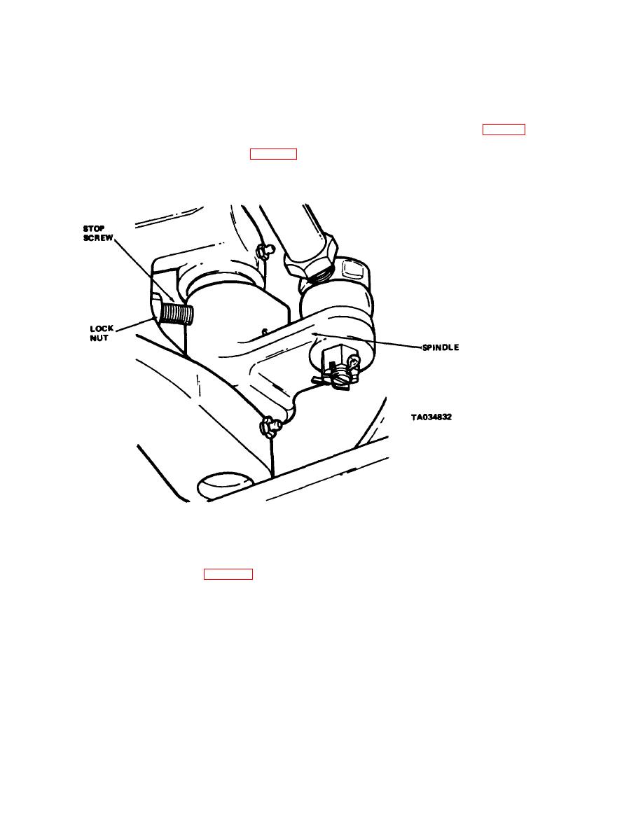
(2) Loosen lock nut (fig. 4-7) and adjust stop
(8) Install ball socket on spindle and secure
screw to stop spindle with proper clearance. Hold stop
with boot (10), nut (11) and cotter pin (12).
screw and tighten lock nuts to secure adjustment.
secured by lock nuts, extend through the axle and
prevent extreme inward pivoting of spindles and to
Figure 4-57. Spindle stop screw adjustment.
d
Drag Link Adjustment.
cotter pin (2) in drag link to secure adjusting plug.
e. Adjustment Checks
(1) Position the rear wheels straight ahead and
parallel with the frame.
(1) Remove blocks and lower rear of truck to
(2) Remove cotter pin (2, fig. 4-58) from the
rest on wheels
end of the drag link (3) and loosen adjusting plug (1).
(2) Sit in operator's seat and operate truck.
(3) Lift drag link from ball stud on pivot arm.
Turn steering wheel to full left and full right positions
(4) Position the cylinder plunger rod halfway
Wheel spindles should contact stop screws in each
out of the steering cylinder (5). Loosen lock nut (4).
direction and cylinder plunger rod should extend and
(5) Turn drag link in or out on cylinder rod.
retract an equal distance.
Place
(3) Shut off truck. Install floor and toe plates.
wrench on flats of cylinder plunger rod to hold rod while
4-75.
Tie Rods and Drag Link
adjusting ball socket. Adjust drag link until it is centered
over pivot arm ball stud with the rear wheels in a straight
a. General . The tie rods connect the axle spindles
ahead position and parallel with the frame.
(6) Connect drag link (3) to ball stud. Tighten
to the steering axle pivot arm. Connection of the
adjusting plug (1) to secure drag link on stud. Install
steering cylinder to pivot arm is accomplished with the
.
adjustable drag link.
4-67
|
|
Privacy Statement - Press Release - Copyright Information. - Contact Us |
