 |
|||
|
|
|||
|
|
|||
| ||||||||||
|
|
 TM 10-3930-630-12
d. Installation.
(5)
Remove adapter ring (6) and thermostat
(5).
(1) Clean elbow mounting surface on cylinder
c.
Test.
head. Remove all rust and gasket material.
(2) Install thermostat (5, fig. 4-54) and adapter
(1) Attach a wire or other means of suspension
ring (6) in outlet elbow (3).
and submerge thermostat in a container of clean water
(3) Use a new gasket (4) and install assembled
(2) Heat water and stir with an accurate
elbow on cylinder head. Secure elbow with nuts (1) and
thermometer. Check water temperature.
lock washers (2).
(3) As the water temperature approaches 180
(4) Connect radiator upper hose (fig. 4-52) to
F (82 C) observe the thermostat. If the thermostat
outlet elbow and secure hose with clamp.
does not start to open at 180 F (82 C) to 200 F (93
(5) Close drain valves and fill radiator with
C) or if it opens well below 180 F (82 C), thermostat
coolant (para 3-12).
must be replaced.
(6) Close side panels and lower seat into
.
position.
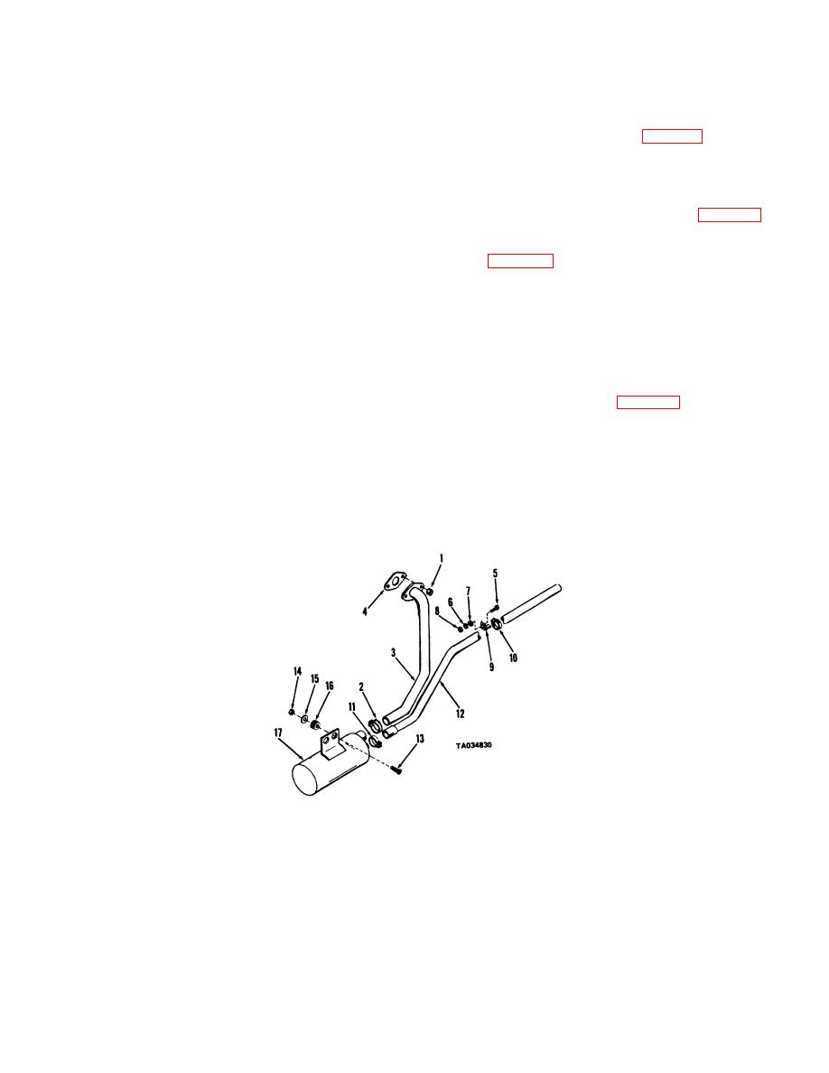
Section XVI. EXHAUST SYSTEM
4-71.
General
(2) If truck has been operating allow sufficient
time to elapse to allow the muffler and pipes to cool.
The exhaust system on the truck consists of a exhaust
(3) Remove nuts (1, fig. 4-55) and disconnect
pipe leading from the manifold to the muffler and a tail
exhaust pipe (3) from manifold. Remove gasket (4)
pipe leading out the rear of the truck The muffler is
Loosen clamp (2) and remove exhaust pipe from truck.
mounted on the lower left side of the truck frame
4-72.
Muffler and Pipes
a. Removal
(1) Open left side panel and lift seat into an
upright position.
TA034830
1
Nut
10
Clamp
2
Clamp
11
Clamp
3
Exhaust pipe
12
Tail pipe
4
Gasket
13
Tail pipe
5
Screw
14
Nut
6
Lock washer
15
Washer
7
Washer
16
Grommet
8
Nut
17
Muffler
9
Support
Figure 4-55. Exhaust system, exploded view
4-65
|
|
Privacy Statement - Press Release - Copyright Information. - Contact Us |
