 |
|||
|
|
|||
|
Page Title:
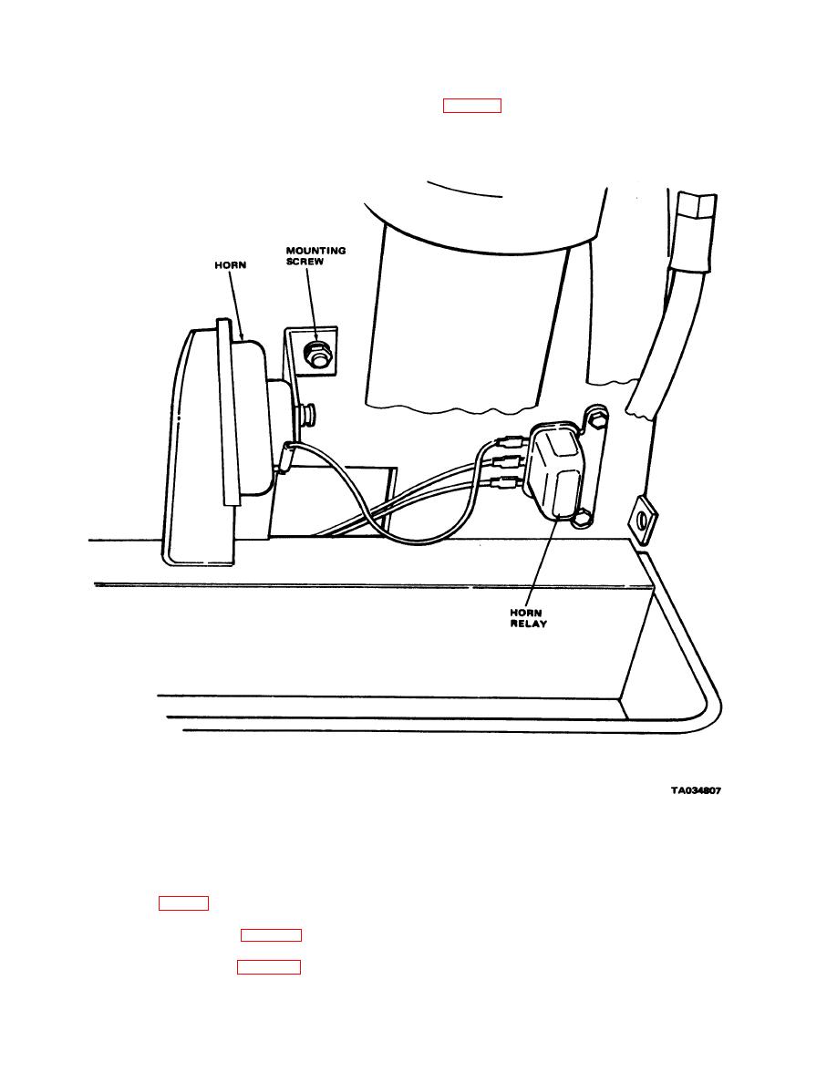
Figure 4-32. Horn and relay, installed view. |
|
||
| ||||||||||
|
|
 TM 10-3930-630-12
weak, replace horn.
(2) Tag and disconnect wires from horn
c. Removal
(1) Remove right front cowl.
Figure 4-32. Horn and relay, installed view.
(3) Remove screw, lockwasher and nut
secure with screw, lockwasher and nut. Connect wires
to horn and relay.
securing horn to frame. Remove horn.
(3) Operate horn button and check horn
operation.
and remove relay (fig. 4-2) from frame.
(4) Install right front cowl.
d. Installation..
secure with screws, lockwashers and nuts.
4-42
|
|
Privacy Statement - Press Release - Copyright Information. - Contact Us |
