 |
|||
|
|
|||
|
Page Title:
Hydraulic Reservoir |
|
||
| ||||||||||
|
|
 TM 10-3930-630-12
on the right side of the frame.
b. Service. Open right side panel to gain
(fig. 424) and install hoses on elbows in filter head.
Tighten clamps securely.
access to the top of the reservoir.
(e) Remove plug from steering
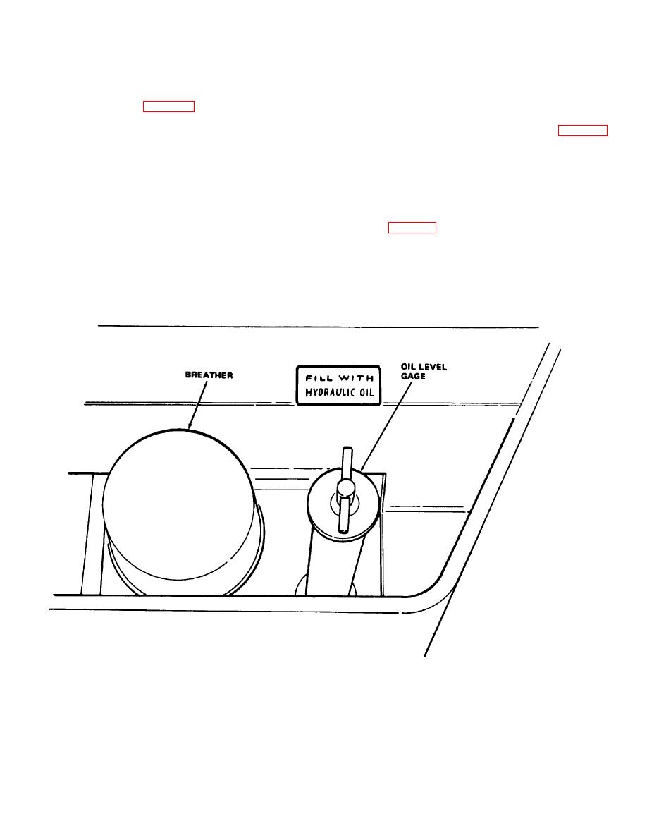
(1) Oil Level.
system return hose (fig. 4-24) and connect hose to
(a) Lower mast and retract all
elbow in filter head inlet elbow.
cylinders.
(f) Check oil level in hydraulic
(b) Remove oil level gage (fig. 4-25)
reservoir and add oil if necessary. Refer to current
and check oil level. Oil level should be to full mark on
lubrication order for correct oil
gage with oil temperature at approximately 70F (21C).
(g) Operate hydraulic system and
(c) Fill reservoir to correct level
check for leaks. Correct if necessary.
Refer to current lubrication order for correct Oil
(h) Bleed hydraulic system (para
(d) Install oil level gage.
434).
(2) Breather and Screen.
Every 200
(I) Install front Cowl
hours the breather should be replaced.
Unscrew
breather (fig. 4-25) from top of reservoir. Install new
4-44.
Hydraulic Reservoir
breather. Remove oil level gage and remove screen.
Clean screen in cleaning compound solvent (P-D-680)
a. General. The hydraulic reservoir serves as
and dry thoroughly. Install screen and gage.
a storage receptacle for the hydraulic oil It is mounted
TA034800
Figure 4-25. Hydraulic reservoir breather and oil level gage..
4-35
|
|
Privacy Statement - Press Release - Copyright Information. - Contact Us |
