 |
|||
|
|
|||
|
|
|||
| ||||||||||
|
|
 TM 10-3930-630-12
position on truck. Block mast as necessary.
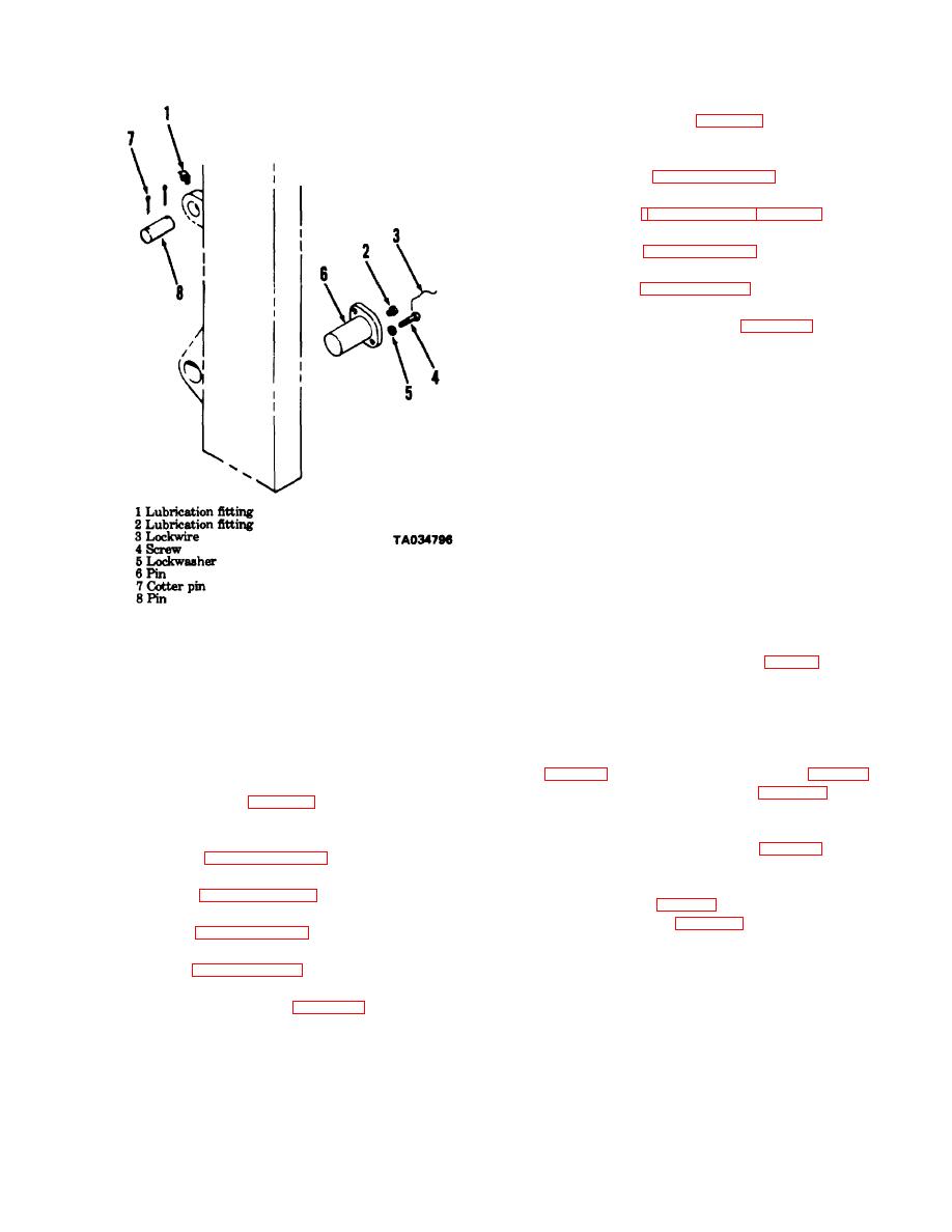
(2) Install pins (6, fig. 4-21) through mast and
frame. Secure pins with screws (4) and lockwashers (5).
Install lockwire (3) to secure screws.
(3) Refer to paragraph 4-37 and connect tilt
cylinders to mast. Remove hoist.
(4) Refer to paragraphs 4-38 and 4-39 and install
cluster and lift cylinders.
(5) Refer to paragraph 4-36 and install carriage,
backrest and forks.
(6) Refer to paragraph 4-35 and install and adjust
lift chains.
(7) Bleed hydraulic system (para 4-34).
(8) Check mast tilt and adjust if necessary (para 4-
37).
(9) Operate lift mechanism and check for smooth
operation.
4-41.
Control Valve Levers
a.
General. Two levers, attached to the control
valve at the right front of the truck, allow the operator to
control lift and tilt functions. When the inner lever is pulled to
the rear, the carriage and mast will lift. When the lever is
pushed forward, the load and carriage will lower. When the
lever is in the center or neutral position, the carriage will
remain where it is halted. The outer lever operates the tilt
function. Pulling the lever to the rear will tilt the mast to the
rear. Pushing the lever forward will tilt the mast forward.
b.
Inspection
(1) Remove screws and remove right-hand cowl
Figure 4-21. Mast mounting, exploded view.
from truck.
(4)
Remove screws (4) and lockwashers (5).
(2) Check control valve levers (fig. 2-1), for secure
Raise mast with hoist to relieve tension on pins.
attachment to control valve.
(7) Remove pins (6) from both sides of mast.
(3) Move levers through entire range of opera-tion.
(8) Use the hoist and lift mast assembly from truck
Movement should be smooth and positive.
and place mast on suitable supports
c.
Removal.
e.
Installation (Model ACC40-24PS100).
(1) Remove nuts and screws attaching control
(1) Use a hoist and lift mast assembly into position
levers (fig. 4-22) to control valve. Remove links (fig. 4-22).
on truck. Block mast as necessary.
(2) Remove retaining rings (fig. 4-22) and pins
(2) Install pins (6, fig. 4-21) through mast and
securing levers to control valve plungers. Remove levers.
frame. Secure pins with screws (4) and lockwashers (5).
d.
Installation.
Install lockwire (3) to secure screws.
(1) Install control valve levers (fig. 4-22) in position
(3) Refer to paragraph 4-37 and connect tilt
on control valve.
cylinders to mast: Remove hoist.
(2) Secure levers to control valve plungers with
(4) Refer to paragraph 4-38 and install cluster
pins and retaining rings (fig. 4-22).
cylinder.
(3) Install links (fig. 4-22) and control levers on
(5) Refer to paragraph 4-36 and install carriage,
control valve. Install screws through levers and links and
backrest and forks.
secure with nuts.
(6) Refer to paragraph 4-35 and install and adjust
(4) Install right hand cowl on truck.
chains.
442.
Hydraulic Filter Element Indicator
(7) Bleed hydraulic system (para 4-34).
a
General The hydraulic filter element indicator is
(8) Check mast tilt and adjust if necessary (para
mounted on the front of the truck next to the control
4437).
(9) Operate lift mechanism and check for smooth
operation.
f.
Installation (Model ACC40-24PS180).
(1) Use a hoist and lift mast assembly into
4-31
|
|
Privacy Statement - Press Release - Copyright Information. - Contact Us |
