| |
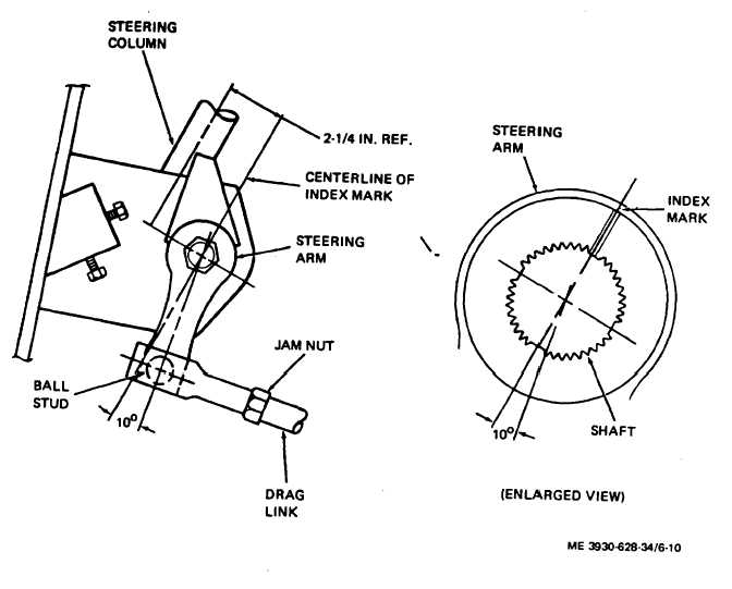
Figure 6-10. Steering arm installation and drag link adjustment.
(2)
With steering arm in position shown on
figure 6-10 (center of ball stud 100 from centerline of
index mark), adjust drag link to match ball stud position.
(3)
Tighten plug in drag link until all end play
is removed. Tighten plug one more turn to align cotter
pin hole and compress spring. Secure plug with cotter
pin.
(4)
With drag link attached to ball stud and
adjusted to remove end play, tighten drag link jam nut
(fig. 6-10) to 90-100 foot-pounds.
b.
Worm Bearing Adjustment.
(1)
Turn steering wheel to end of travel in
either direction. To check worm bearing preloading,
place a torque gage on the steering shaft and turn
steering wheel back approximately one-quarter turn.
Torque reading must be 3/4- 1/4 foot pounds (6 3/4--11
3/4 inch-pounds).
(2)
Adjust preloading as follows:
(a)
Place drain pan under steering gear
housing. Drain lubricant.
(b)
Remove capscrews (21, fig. 6-9)
and loosen cap (22).
(c)
If torque reading is greater than that
specified, add extra shims (231. If reading is less than
that specified, remove shims.
(d)
Tighten capscrews (21) to 24-35
foot- pounds.
(e)
Refill housing with lubricant, install
filler plug. Recheck preload with torque gage. If reading
is not within specifications, add or subtract shims one at
a time, tightening capscrews and checking reading each
time.
c.
Worm and Roller Mesh Adjustment.
(1)
Center the steering wheels and disconnect
drag link from steering arm.
(2)
Count number of full turns of steering
wheel from one extreme to the other. One-half total
number of turns is mid-position.
(3)
With wheel at mid-position, attach drag
link to steering arm.
(4)
Place torque gage on steering shaft.
Swing wheel one-quarter turn. Torque reading must be
2-3 1/2 foot-pounds (18-31 1/2 inch-pounds).
(5)
Adjust worm and roller mesh as follows:
6-13
|