 |
|||
|
|
|||
|
|
|||
| ||||||||||
|
|
 TM 10-3930-628-12
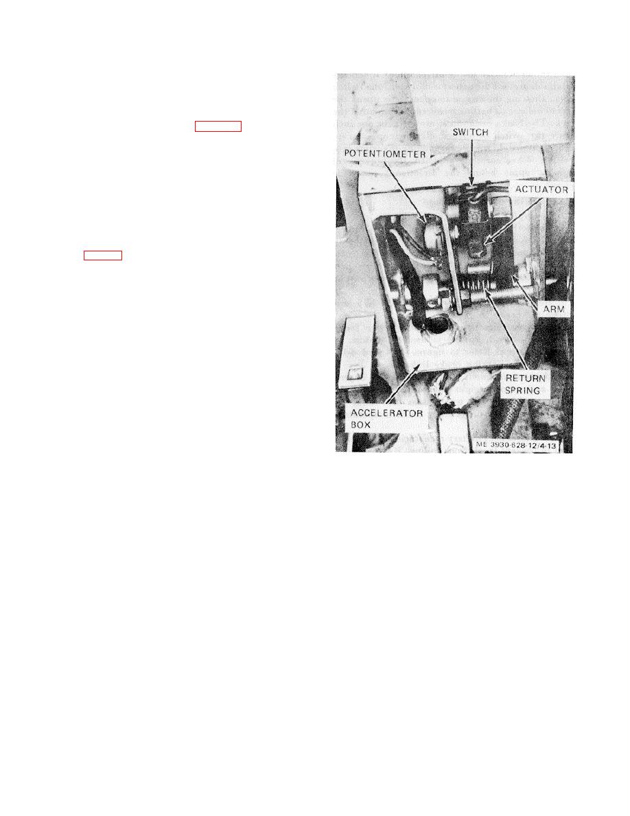
c. Accelerator Control. This control is located
on the front part of the frame to the left of the steering
column. Remove the cover from the box to gain access
to the components. Inspect components as follows:
(1) Check potentiometer (fig. 4-13) for secure
mounting and operation.
(2) Check switch, actuator, and arm for proper
operation. Depress accelerator and observe operation of
switch and potentiometer.
(3) Inspect.
return spring for cracks and
damage. Operate accelerator and observe action of
return spring.
d. Forward and Reverse Switch. The forward
and reverse switch is mounted in a box below the
instrument panel. To inspect the switch, remove cover
from box (fig. 4-1). Inspect switch for secure wiring and
damage. Install cover on box.
e. Harness Wiring.
Inspect the wiring
harnesses for damage, broken wires, damaged
insulation, loose terminals, and insecure mounting.
Repair and tighten terminals. Tape or cover damaged
insulation. Connect broken wires, if possible. Tighten
mounting clamps and ties, if necessary.
Figure 4-13. Accelerator control box, installed view.
Section IX. BRAKES
4-31.
General
seat opens the switch and removes power from all
a. Brakes on the fork lift truck consist of two
electrical circuits.
systems: a seat operated parking brake on the drive
c. The service brakes are hydraulically
motor shaft and service brakes on the two front wheels.
actuated through a pedal and master cylinder.
b. The parking brake is a dual-shoe
Depressing the pedal operates the master cylinder
mechanical operated type. Actuation of the brake is ac-
sending hydraulic pressure to the wheel cylinders. The
complished through a linkage connected to the hinged
wheel cylinders are the double end type and hydraulic
operator's seat. When the operator leaves the seat or
pressure extends the ends of the cylinder, pivoting the
stands up, removing his weight from the seat, the brake
brake shoes against the brake drum inside the wheel.
is applied. A spring at the lower end of the linkage
The pressure in the master cylinder also closes the
expands and moves the brake actuating lever which
stoplight switch and operates the stoplight. When the
forces the brake shoes against brake drum. This
pedal is released, springs return the pedal and brake
pressure keeps the shaft from rotating, locking the front
shoes to the released position.
wheel and holding the truck in position. A seat switch is
d. A brake interlock switch is employed in the
actuated by the linkage when the seat is raised or
electrical system to reduce the amount of load on the
lowered. The switch is closed when the seat is down.
drive motor and conserve battery current. The switch is
Raising the
a normally open switch and is held closed
4-15
|
|
Privacy Statement - Press Release - Copyright Information. - Contact Us |
