 |
|||
|
|
|||
|
Page Title:
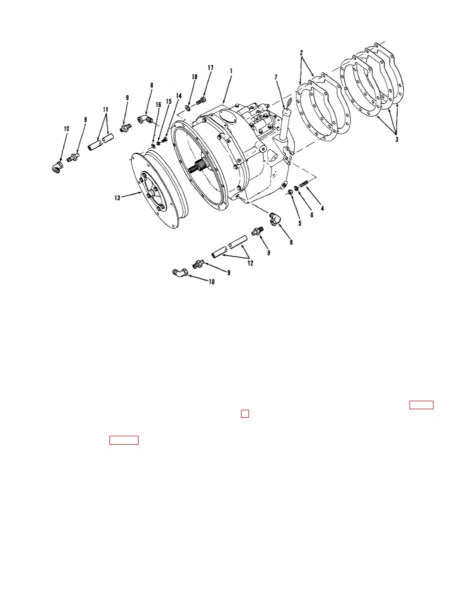
Figure 7-5. Transmission arrangement. |
|
||
| ||||||||||
|
|
 ME10-3930-627-34/7-5
1.
Transmission
10.
Street elbow
2.
Gasket (.005)
11.
Hose
3.
Gasket (.010)
12.
Hose
4.
Stud
13.
Torque converter
5.
Nut
14.
Capscrew
6.
Lock washer
15.
Lock washer
7.
Dipstick
16.
Washer
8.
Street elbow
17.
Cap screw
9.
Fitting
18.
Lock washer
Figure 7-5. Transmission arrangement.
7-8. Transmission Disassembly
a. Remove transmission from truck.
(1) Remove snap rings (39 and 40) holding
b. Remove cap screws and washers attaching control
bearing (38).
valve and remove valve from transmission.
(2) Remove snap rings (33).
(3) Tap end of forward drive shaft (37) and while
case adapter (4) to insure proper reinstallation, and
holding forward gear (36) and pull shaft out thru opening
remove screws (25) and washers (5) holding pump to
in housing.
adapter.
g. Remove the reverse gear and shaft in the following
d. Lay transmission on case rear half and remove cap
manner:
screws (17 and 18) and washers (19) holding adapter to
(1) Remove snap ring (33) holding bearing (34).
transmission case. Lift off front case and clutch pack as
(2) Scribe or punch mark the bearing retainer (41)
a unit.
with the gear case to insure proper reinstallation.
e. Separate the clutch pack assembly from the front
case assembly by sliding clutch pack from front case.
7-7
|
|
Privacy Statement - Press Release - Copyright Information. - Contact Us |
