 |
|||
|
|
|||
|
|
|||
| ||||||||||
|
|
 brushes in holders after alternator is assembled. This
6-7. Starting Motor Disassembly and Inspection
will allow brushes to drop on slip rings.
6-4. Alternator Test and Installation
Do not disassemble further than necessary to locate
After installation, check and if necessary adjust
damaged parts.
regulator, TM 10-3930-627-12.
b. Check for worn brushes (4). Replace if worn to half
6-5. Starting Motor Removal and Installation
the length of a new brush from stock. Make sure brush
See TM 10-3930-627-12.
holders (6) are clean and that brushes are not binding in
holders. Check tension of brush spring (8); it must be
6-6. Starting Motor Test
35 ounces minimum.
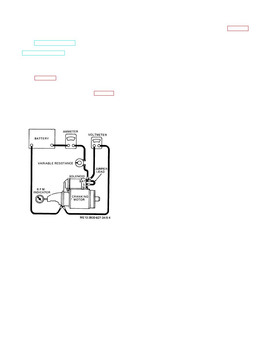
a. Connect starting motor in series with fully-charged,
c. Check armature (15) for shorting by using a
12-bolt battery, an ammeter capable of reading several
growler. Shorts are sometimes caused by brush or
hundred amperes, and a variable resistor in a setup as
copper dust between copper commutator bars.
shown in figure 6-4. Connect negative battery lead to
Undercut commutator insulation to eliminate these
starting motor frame.
shorts.
d. Check for open armature windings by checking for
frame and to motor terminal as shown in figure 6-4.
loose connections between commutator risers and ends
of windings. Poor connections cause arcing and burning
of commutator. If commutator bars are not too badly
is indicated on voltmeter.
burned, resolder leads to bars and turn down
commutator in lathe. Undercut commutator insulation to
tachometer. Current draw must be 50 to 80 am-peres.
1/32 inch lower than commutator bar surface.
Speed must be 5500 to 10, 500 rpm.
e. Check for grounds in armature, using test lamp. If
lamp lights when one probe is placed on commutator
and the other is on shaft or core, armature is grounded
and will need replacement.
f. Check field coils for grounds with test lamp.
Connect one probe of test lamp to field frame and other
to field connector.
If lamp lights, field coils are
grounded and must be replaced.
g. Check field coils (39 and 40) for opens with test
lamp. Apply probes to ends of field coils. If lamp fails
to light, field coils are open, and must be replaced.
Figure 6-4. Starting motor test setup.
6-5
|
|
Privacy Statement - Press Release - Copyright Information. - Contact Us |
