 |
|||
|
|
|||
|
Page Title:
Figure 3-4. Crankshaft and related parts, exploded view. |
|
||
| ||||||||||
|
|
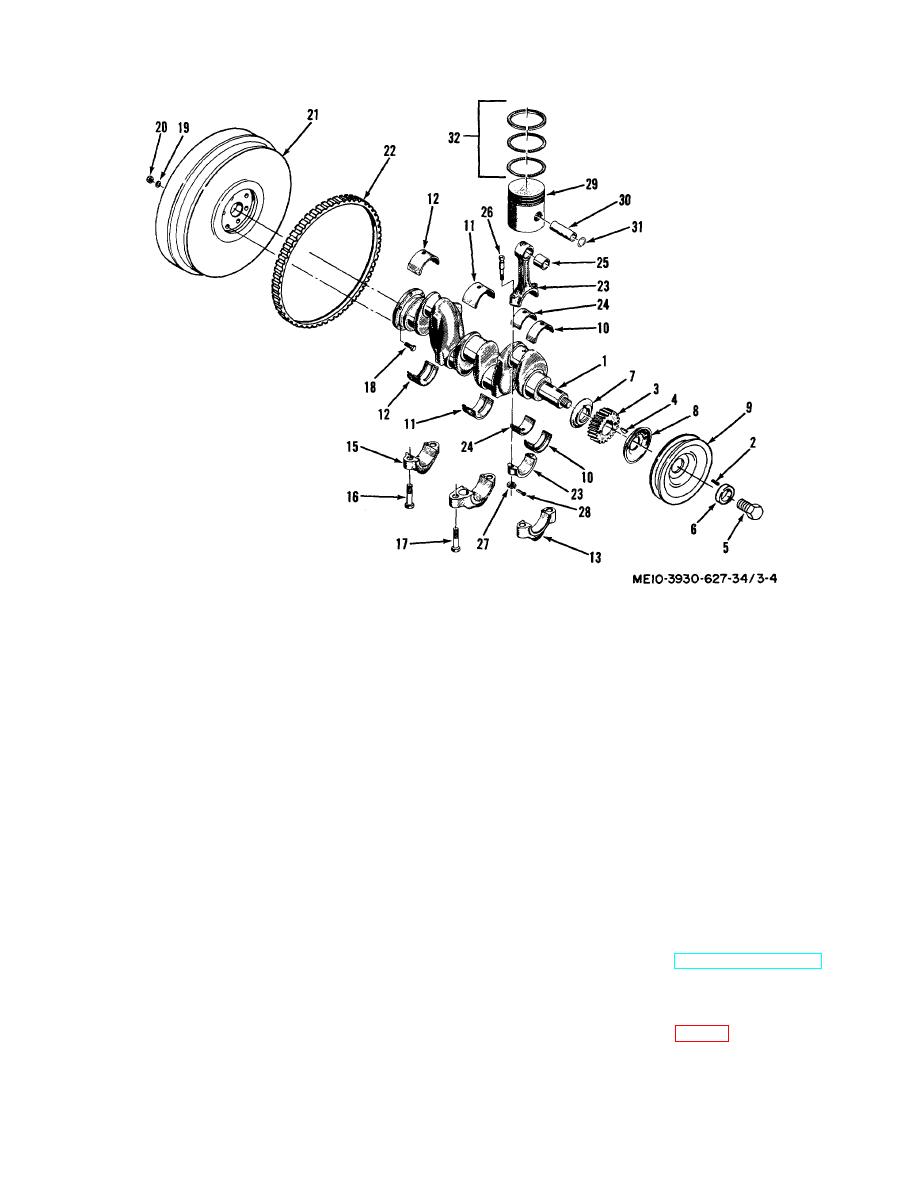 1.
Crankshaft
17.
Bolt
2.
Keyway plug
18.
Flywheel bolt
3.
Crankshaft timing gear I
19.
Lock washer
4.
Key
20.
Nut
5.
Crankshaft screw
21.
Flywheel assembly
6.
Crankshaft pulley washer
22.
Ring gear
7.
Thrust plate
23.
Connecting rod assembly
8.
Oil slinger
24.
Rod bearing
9.
Pulley
25.
Piston pin bushing
10.
Front main bearing
26.
Bolt
11.
Center main bearing
27.
Nut
12.
Rear main bearing
28.
Cotter pin
13.
Front main bearing cap
29.
Piton
14.
Center main bearing cap
30.
Piston pin
15.
Rear main bearing cap
31.
Retaining ring
16.
Bolt
32.
Piston ring set
Figure 3-4. Crankshaft and related parts, exploded view.
(7) After valves and seats have been refaced,
e. Installation. Reverse procedure in step a. above.
check the width of the valve face contact with the seat.
f. Adjust Valves. Refer to TM 10-3930-627-12.
The width should be 1/16 to 3/32 inch. If the width of
the contact surface exceeds 3/32 inch, the seat in the
3-6. Crankshaft Pulley
block may be narrowed by using a 15 stone to reduce
a. Removal.
the outside diameter or a 75 stone may be used to
(1) Remove screw (5, fig. 3-4) and washer 16).
increase the inside diameter in the valve seat.
(2) Remove pulley (9), using a puller
3-4
|
|
Privacy Statement - Press Release - Copyright Information. - Contact Us |
