 |
|||
|
|
|||
|
Page Title:
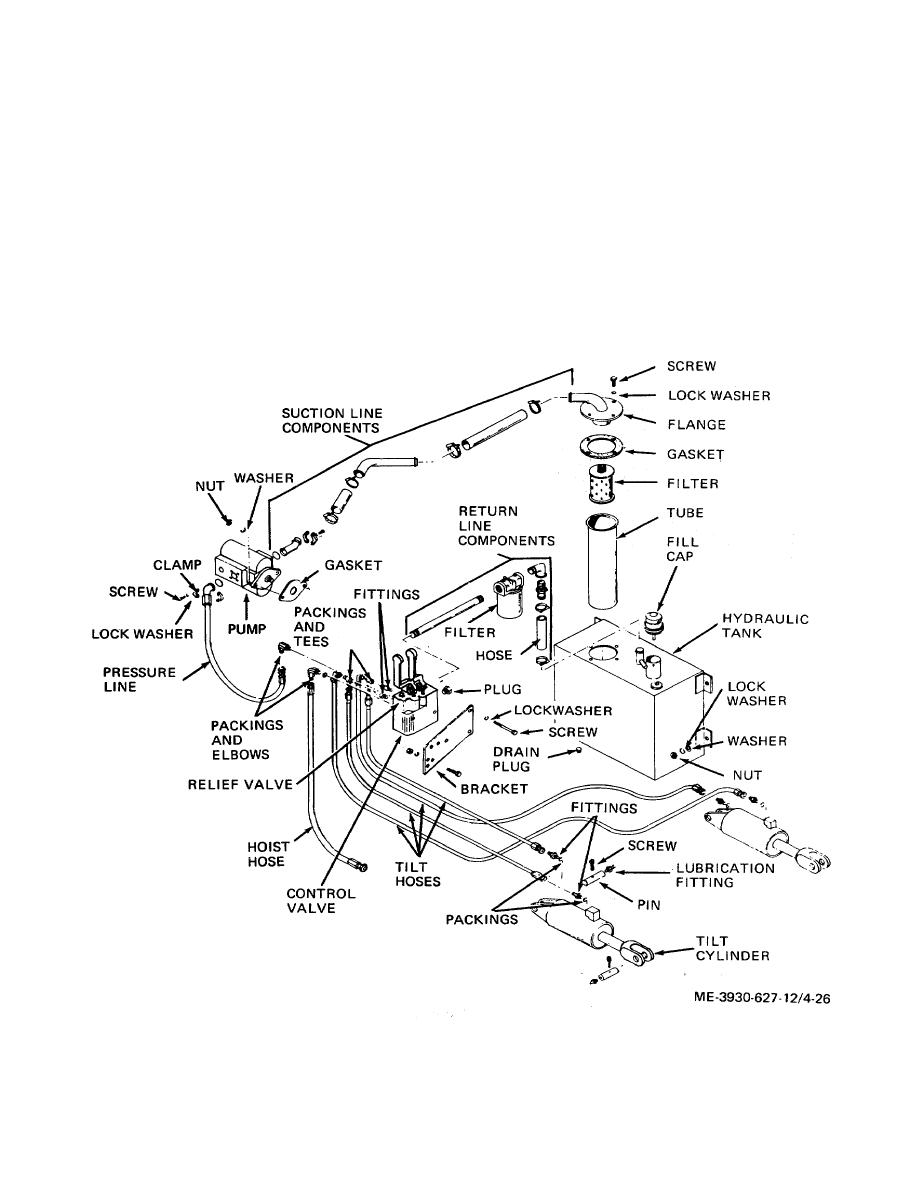
Figure 4-26. Hydraulic system layout. |
|
||
| ||||||||||
|
|
 TM 10-3930-627-12
dismounted valve is to be adjusted for return to stock,
(6)
When levers are positioned
use same procedure, getting hydraulic pressure from a
satisfactorily, install three cotter pins to secure shaft.
hydraulic test set, and plug ports before storing valve.
(7) Disconnect upper TILT hose, and insert
Proceed as follows:
a hydraulic pressure gage scaled to read to 2000 pounds
(2) Install control valve by reversing step a
per square inch in TILT hose port.
above.
(8) Remove cap nut at top right side of the
(3)
Reinstall hoses according to tags
control valve and insert a screwdriver in slot of adjusting
attached at removal, in valve ports from which they
setscrew. With engine running move TILT control lever
came. Install packing and elbows, then screw adapters
to UP position, and turn adjusting
setscrew as
into elbows.
necessary to cause pressure gage to indicate 1700 to
(4) Reconnect return hose to adapter and
1900 pounds per square inch. Lock adjustment with nut
tighten hose clamp.
and recheck setting after tightening nut.
(5) Install shaft through HOIST and TILT
levers, spacing levers with spacers within bracket.
Figure 4-26. Hydraulic system layout.
4-33
|
|
Privacy Statement - Press Release - Copyright Information. - Contact Us |
