 |
|||
|
|
|||
|
Page Title:
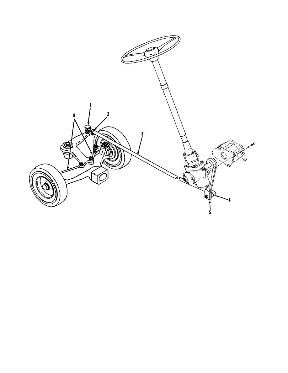
Figure 4-25. Steering arrangement. |
|
||
| ||||||||||
|
|
 TM 10-3930-627-12
1. Drag link end
4. Drag link end
2. Clamp
5. Steering arm
3. Drag link
6. Tie rods
Figure 4-25. Steering arrangement.
truck hydraulic system. No service is required.
4-49. Steering Gear
The steering gear is lubricated by fluid from the
Section XV. HYDRAULIC LIFT COMPONENTS
(2) Remove screws, nuts, and washers
4-50. Control Valve Maintenance
attaching the valve to the mounting bracket and take off
a. Removal (fig. 4-29).
the valve.
(1)
Tag hoses to identify them for
b. Installation and Adjustment.
reconnection and disconnect them at the valve. Strip
(1)
Adjustment procedures given here
valve of fittings and cap or plug hoses to keep dirt out.
presume the valve is installed on a serviceable truck. If
Save any usable fittings.
4-32
|
|
Privacy Statement - Press Release - Copyright Information. - Contact Us |
