 |
|||
|
|
|||
|
|
|||
| ||||||||||
|
|
 TM 10-3930-627-12
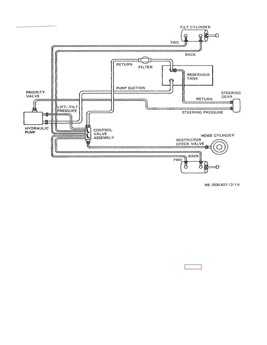
Figure 1-5. Hydraulic System.
h. Electrical Units.
resistance winding to change the current in the gage
(1) Spotlight. The sealed-beam spotlight is
circuit proportional to the fuel level, which is registered
on the instrument.
mounted on the left hand hoist upright. This light is
(5) Oil pressure sending unit. The oil
operated by a toggle switch mounted on the instrument
pressure sending unit is connected into the pressure side
panel. The switch mounted on the spotlight itself is
of the lubricating oil system. This unit contains a coil,
bypassed, and will not operate the light.
(2) Combination tail and stop light. The tail
the resistance of which varies with pressure. Actuating
current to the instrument passes through this resistance
and stop light is mounted within a steel guard on the
coil which varies the current, and thus the indication, in
upper rear of the engine compartment. The taillight
proportion to the pressure on the sending unit.
operates when the spotlight is turned on. The stop light
(6) Coolant temperature sending unit. The
is operated by the brake light switch when the foot
coolant temperature sending unit is threaded into the
brakes are used.
(3) Ignition switch. The ignition switch is
engine cylinder head (fig. 1-2) to sense and respond to
engine coolant temperature.
This unit contains a
mounted on the instrument panel. Setting the ignition
temperature sensitive resistance coil
switch to ON position energizes the ignition system and
instrument panel gages.
(4) Fuel gage sending unit. The fuel gage
sending unit is mounted atop the fuel tank. This unit
consists of a float mounted on an arm attached to a
sliding contact. The position of the arm is proportional to
the quantity of fuel. The slider shorts out turns of a
1-7
|
|
Privacy Statement - Press Release - Copyright Information. - Contact Us |
