 |
|||
|
|
|||
|
Page Title:
Section VI. REPAIR OF STEERING SYSTEM |
|
||
| ||||||||||
|
|
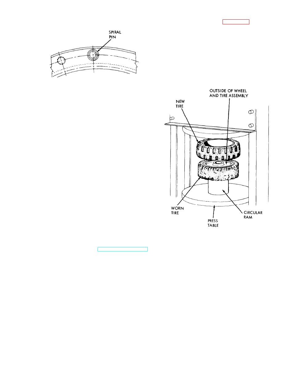 a circular ram having a smaller outside diameter
than the tire inside diameter and place in a 100 ton
or larger hydraulic press. See figure 4-25. Position
the new tire on top of the old tire. Run the press
slowly for the first few inches of travel. If the tire
begins to cock, stop and realign it. A sharp tap with
a soft headed mallet will usually do this. Continue
pressing until the old tire is off and the new tire is
correctly positioned on the wheel. Make sure the
rim of the new tire is pressed onto the wheel to the
same location as the original.
ME 3930-324-34/4-24
Figure 4-24. Spiral pin installation.
(e) Position the bull gear, bottom side
down, in the drive wheel. Aline the spiral pins with
the holes in the drive wheel and tap the bull gear
evenly to start it into the drive wheel.
(f) Install the capscrews which were
originally removed and alternately tighten the
capscrews and tap the bull gear until the gear is
seated. Try to insert a 0.003 inch feeler gage
between the gear and the shoulder. When the gear
is properly seated, the gage will not enter at any
point. Tighten the capscrews to a torque of 28 to 32
ft lbs.
(3) Brake drum.
(a) When resurfacing the brake drums,
follow the resurfacing equipment manufacturer's
instructions. Always resurface both drums of the
truck to an equal diameter.
(b) Finish grind or hone the drums to
remove cutting tool marks. Otherwise, linings will
wear rapidly. If a brake drum surface requires
machining to a diameter greater than 0.030 inch
beyond original diameter, t h e w h e e l m u s t b e
discarded. Thin drums may break under strain.
Original brake drum surface diameter is 13.135 to
13.143 inches.
ME 3930-624-34/4-25
d. Reassembly. Assemble the wheel in the
Figure 4-25. Tire replacement.
reverse order of disassembly.
e. Installation. Refer to TM 10-3930-624-12.
4-16. Tire Replacement
Place the old wheel, with the chamfered side up, on
Section VI. REPAIR OF STEERING SYSTEM
4-17. General
hydraulic, with no mechanical connection between
The steering system consists of the steering wheel,
the column assembly and the cylinder. The base of
column and valve assembly, the power steering
the cylinder is anchored to the frame. The pivot
cylinder and the steer axle assembly. Oil for the
arm is connected to the steer wheel spindles by two
power steering system is supplied by the hydraulic
tie rods.
pump. w h i c h a l s o s e r v e s t h e t r u c k h y d r a u l i c
system. The power steering system is fully
4-27
|
|
Privacy Statement - Press Release - Copyright Information. - Contact Us |
