 |
|||
|
|
|||
|
|
|||
| ||||||||||
|
|
 ME 3930-624-34/4-21
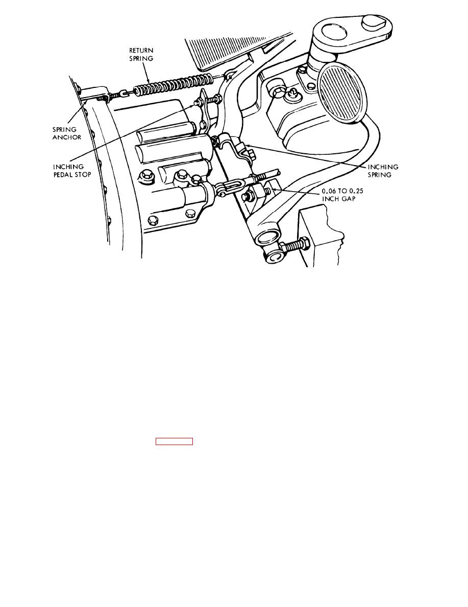
Figure 4-21. Inching pedal mechanical adjustment.
(b) Install the return spring (normal length
(a) Install a 160 or 300 psi pressure gage at
10 in.). Tighten the spring until it is 11-11 in.
the pressure port of the powershift control cover.
(b) Depress the brake pedal until the brake
long.
(c) Position the inching spring against the
shoes engage the drum. A slight resistance will be
plunger so that the deflection is 3/32-1/8 in.
felt in pedal movement.
(d) Raise the drive wheels off the floor, start
(c) Place a wedge between the brake return
the engine and operate at high idle, and shift the
stop and the pedal lug to fix the position of
transmission into forward or reverse gear. The
engagement.
(d) Engage the parking brake.
inching valve plunger must not move forward.
(e) Lower the wheels to the ground. engage
(e) Start the engine and operate at low idle
the brakes, and place the transmission in gear. The
(500 to 600 rpm). Place the transmission in neutral
engine should approach a stall. Shut down the
and keep the seat deck down. Depress the inching
engine.
pedal until the pressure gage reads 6 to 10 psi.
(2) Hydraulic adjustment. (fig. 4-22.)
Note. Do not perform hydraulic adjustments until the
mechanical adjustments are correct.
4-24
|
|
Privacy Statement - Press Release - Copyright Information. - Contact Us |
