 |
|||
|
|
|||
|
Page Title:
Section II. REPAIR OF FRONT AXLE ASSEMBLY |
|
||
| ||||||||||
|
|
 (7) Inspect the separator plate, valve body and
solvent. Dry with compressed air. Blow out all the
valve cover for cracks, chips, nicks, dents and other
passages in the valve body.
damage. Repair or replace as required.
(2) Perform general inspection procedures.
d. Reassembly. Assemble the valve in the
(3) Inspect the valve plungers and spools for
reverse order of disassembly. Lubricate parts
scoring and wear, Remove surface blemishes with a
lightly with transmission oil before assembling.
soft hone or crocus cloth. Replace if wear is ex-
Ensure that plungers and spools operate freely.
cessive.
Install the stops at the selector valve plunger and
(4) Inspect springs for cracks or weakness.
the inching valve plunger so that the angled edges
Replace if necessary.
face the back of the valve body.
( 5 ) I n s p e c t s p r i n g retainers for damage.
e. Installation. Install the valve by reversing the
Replace as required.
removal procedure.
( 6 ) I n s p e c t t h e d e t e n t b a l l f o r f l a ts p o t s .
Smooth surfaces or replace.
Section II. REPAIR OF FRONT AXLE ASSEMBLY
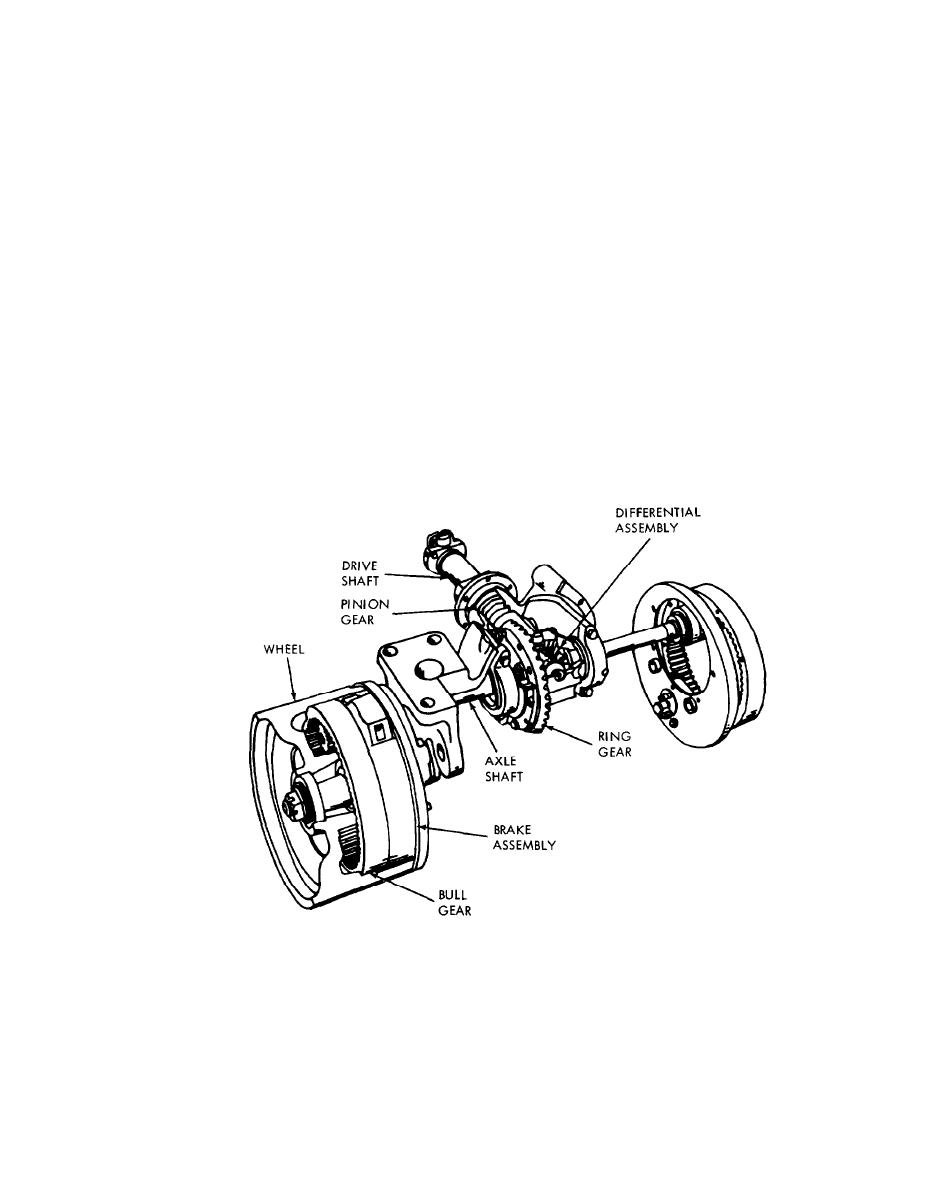
ferential carrier is mounted at the center of the
4-5. General
drive unit housing. Final reduction is obtained
The front (drivel axle assembly is a double
through an internal tooth ring gear (bull gear)
reduction, spiral bevel and internal gear drive. The
inside the drive wheel, in addition to the usual
drive wheels, bevel drive pinion, and differential
reduction at the differential pinion and ring gear.
assembly are supported by tapered roller bearings.
Figure 4-13 shows a cutaway view of the front axle
The axle drive shafts (jack shafts), which are used
assembly.
only for torque transfer and carry no weight, are
supported by double thrust bearings. The dif-
ME 3930-624-34/4-13
Figure 4-13. Front axle assembly, cutaway view.
4-11
|
|
Privacy Statement - Press Release - Copyright Information. - Contact Us |
